Transmission system and method employing electrical return-to-zero modulation

a technology of electrical return to zero and transmission system, applied in electromagnetic transmission, electrical apparatus, transmission, etc., can solve the problems of high cost, large mz modulator, and unfit high-speed long-range optical networks, and achieve the effect of reducing the size and cost of optical transmitters, and improving the performan

Inactive Publication Date: 2006-06-08
FUTUREWEI TECH INC
View PDF5 Cites 3 Cited by
  • Summary
  • Abstract
  • Description
  • Claims
  • Application Information

AI Technical Summary

Benefits of technology

[0020] Many benefits are achieved by way of the present invention over conventional techniques. Some embodiments of the present invention provide superior performance with EMLs of fixed or tunable laser wavelength. As an example, with widely tunable 2.5-Gbps EML, optical signals under eRZ modulation can achieve error-free transmission over 400 kilometers with more than 5-dB OSNR margin without using any dispersion compensation or forward error correction (FEC). Such EML includes an EAM with bulk semiconductor. As another example, for EML with fixed or narrowly tunable wavelength, optical signals under eRZ modulation can achieve error-free transmission over 600 kilometers with more than 5-dB OSNR margin without using any dispersion compensation or FEC. Such EML includes an EAM with multiple quantum wells. In contrast, a conventional EML that includes EAM with bulk semiconductor can usually provide error-free transmission for only about 200 kilometers in single mode optical fiber. A conventional EML including EAM with multiple quantum wells can usually provide error-free transmission for only about 400 kilometers in single mode optical fiber. Certain embodiments of the present invention provide an optical transmitter that would enable wide utilization of 2.5-Gbps EMLs to optical transport systems without dispersion compensation beyond the conventional limit on transmission distance.
[0021] Some embodiments of the present invention reduce size and cost of optical transmitters at various data rates, such as 2.5 Gbps. As an example, for conventional NRZ EMLs including EAM with multiple quantum wells, it may be possible to cherry-pick a few units which give desirable chirp characteristics, but these units often incur high premium due to a low yield rate. As another example, for metro and regional optical transport systems, flexibility at low cost in compact size is the key to broadband development. Certain embodiments of the present invention eliminate the need for dispersion compensation at various data rates and over several hundred kilometers. Adding dispersion compensation modules may reduce chromatic dispersion related distortions and / or timing jitters, but would greatly increase costs and reduce network flexibility such as at add / drop sites. Therefore transmitters employing EMLs but requiring no dispersion compensation is highly desirable. For example, a transmitter according to one embodiment of the present invention can perform error-free transmission at data rate of 2.5 Gbps over several hundred kilometers of single mode fiber without using any dispersion compensation. Certain embodiments of the present invention provide eRZ modulation with an EML that can be tuned to operate at any wavelength grids in C band or L band for dense wavelength division multiplexing (DWDM). For example, an optical transmitter according to an embodiment of the present invention is used for reconfigurable DWDM optical networks.

Problems solved by technology

Additionally, the dispersion-limited distance can be adversely affected by chirp in a modulated optical signal.
Accordingly, a transmitter with directly modulated semiconductor laser (DML) is often considered unfit for high-speed long haul optical networks.
But the MZ modulator is often bulky, expensive, and complicated to operate.
But the conventional electroabsorption modulator suffers from significant drawbacks.
For example, the conventional MQW EAM often requires a wavelength match between laser and electroabsorption, and thus limits the manufacturing yield.

Method used


Image

  • Transmission system and method employing electrical return-to-zero modulation
  • Transmission system and method employing electrical return-to-zero modulation
  • Transmission system and method employing electrical return-to-zero modulation

Examples


Embodiment Construction

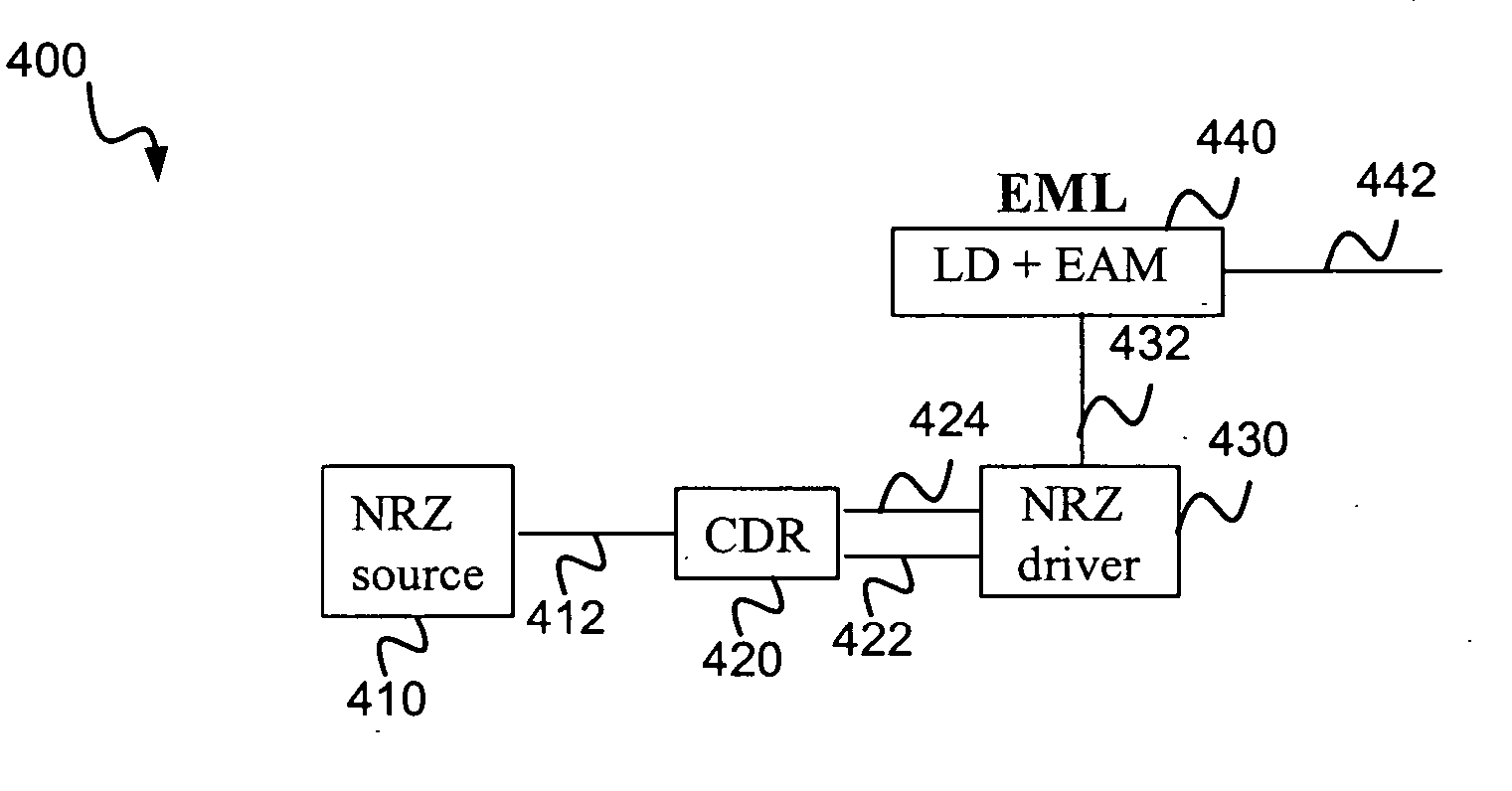
[0033] The present invention relates in general to telecommunication techniques. More particularly, the invention provides a method and system using an electroabsorption modulated laser (EML) with electrical return-to-zero (eRZ) modulation. Merely by way of example, the invention is described as it applies to optical networks, but it should be recognized that the invention has a broader range of applicability.

[0034] For a conventional EML, the non-return-to-zero (NRZ) modulation is usually applied. The NRZ modulation is perceived conventionally as being more tolerant to chromatic dispersion than RZ modulation because the NRZ modulation has a narrower spectrum. For example, a chirp-free transform-limited NRZ data pulse can give rise to a spectral width of 0.013 nm at 2.5 Gbps and 1550 nm based on the second moment calculation. Such chirp-free NRZ signal can theoretically tolerate a maximum chromatic dispersion of 18,820 ps / nm at 1-dB power penalty. This maximum dispersion tolerance ...


PUM


Abstract

A system and method for transmitting a signal for optical network applications. The system includes an optical transmitter configured to output an optical signal. The optical signal is associated with a return-to-zero modulation. Additionally, the system includes an optical fiber transmission system coupled to the optical transmitter and configured to transmit the optical signal and output the transmitted optical signal. The optical transmitter includes a return-to-zero driver configured to receive at least a first data signal and generate a drive signal, a light source configured to generate a laser, and an electroabsorption modulator configured to receive the laser and the drive signal and generate the optical signal. Each of the first data signal and the drive signal is an electrical signal. The optical signal includes data associated with the return-to-zero modulation. The optical fiber transmission system is free from any dispersion compensation device.

Description

CROSS-REFERENCES TO RELATED APPLICATIONS [0001] NOT APPLICABLE STATEMENT AS TO RIGHTS TO INVENTIONS MADE UNDER FEDERALLY SPONSORED RESEARCH OR DEVELOPMENT [0002] NOT APPLICABLE REFERENCE TO A “SEQUENCE LISTING,” A TABLE, OR A COMPUTER PROGRAM LISTING APPENDIX SUBMITTED ON A COMPACT DISK. [0003] NOT APPLICABLE BACKGROUND OF THE INVENTION [0004] The present invention relates in general to telecommunication techniques. More particularly, the invention provides a method and system using an electroabsorption modulated laser (EML) with electrical return-to-zero (eRZ) modulation. Merely by way of example, the invention is described as it applies to optical networks, but it should be recognized that the invention has a broader range of applicability. [0005] Telecommunication techniques have progressed through the years. As merely an example, optical networks have been used for conventional telecommunications in voice and other applications. The optical networks can transmit multiple signals...

Claims


Application Information

Patent Timeline
Patent Type & Authority Applications(United States)
IPC IPC(8): H04B10/12
CPCH04B10/5162H04B10/541
Inventor BAI, YU SHENGZHU, FEI
Owner FUTUREWEI TECH INC
Why Eureka
Try Eureka