Gas chromatography/mass spectrometry system

a mass spectrometry and gas chromatography technology, applied in the direction of dispersed particle separation, instruments, separation processes, etc., can solve the problems of reducing analytical efficiency, consuming effort and time, and preparing two gc/ms's, so as to maintain stability of mass spectrometers, high reliability, and efficient performance

Active Publication Date: 2006-06-15
SHIMADZU CORP
View PDF3 Cites 21 Cited by
  • Summary
  • Abstract
  • Description
  • Claims
  • Application Information

AI Technical Summary

Benefits of technology

[0023] By virtue of the gas chromatography/mass spectrometry system according to the present invention, the analysis of samples of different types and different properties, such as, for example, agricultural chemicals and volatile organic compounds, can be performed selectively with one system. Even when different analyses are to be performed, by controlling the combination of sample introduction parts and columns, the analyses can be performed virtually continuously, without having to temporarily stop the device. Therefore, the analyses can be performed efficiently while controlling the expense associated with introduction of the samples to the system. Furthermore, even when performing different analyses, because there is no need to repeatedly start and stop the

Problems solved by technology

However, because preparing two GC/MS's is expensive, a conventional approach has been to perform agricultural chemical analysis and volatile organic compound analysis by suitably switching with one GC/MS.
Such operations take effort and time, and the analytical efficiency is degraded.
Also, as a result of repeated stopping and starting of the device, instabilities easily arise.
F

Method used


Image

  • Gas chromatography/mass spectrometry system
  • Gas chromatography/mass spectrometry system
  • Gas chromatography/mass spectrometry system

Examples


Embodiment Construction

[0027] In the following description, a GC / MS system according to one embodiment of the present invention is described with reference to the accompanying drawings.

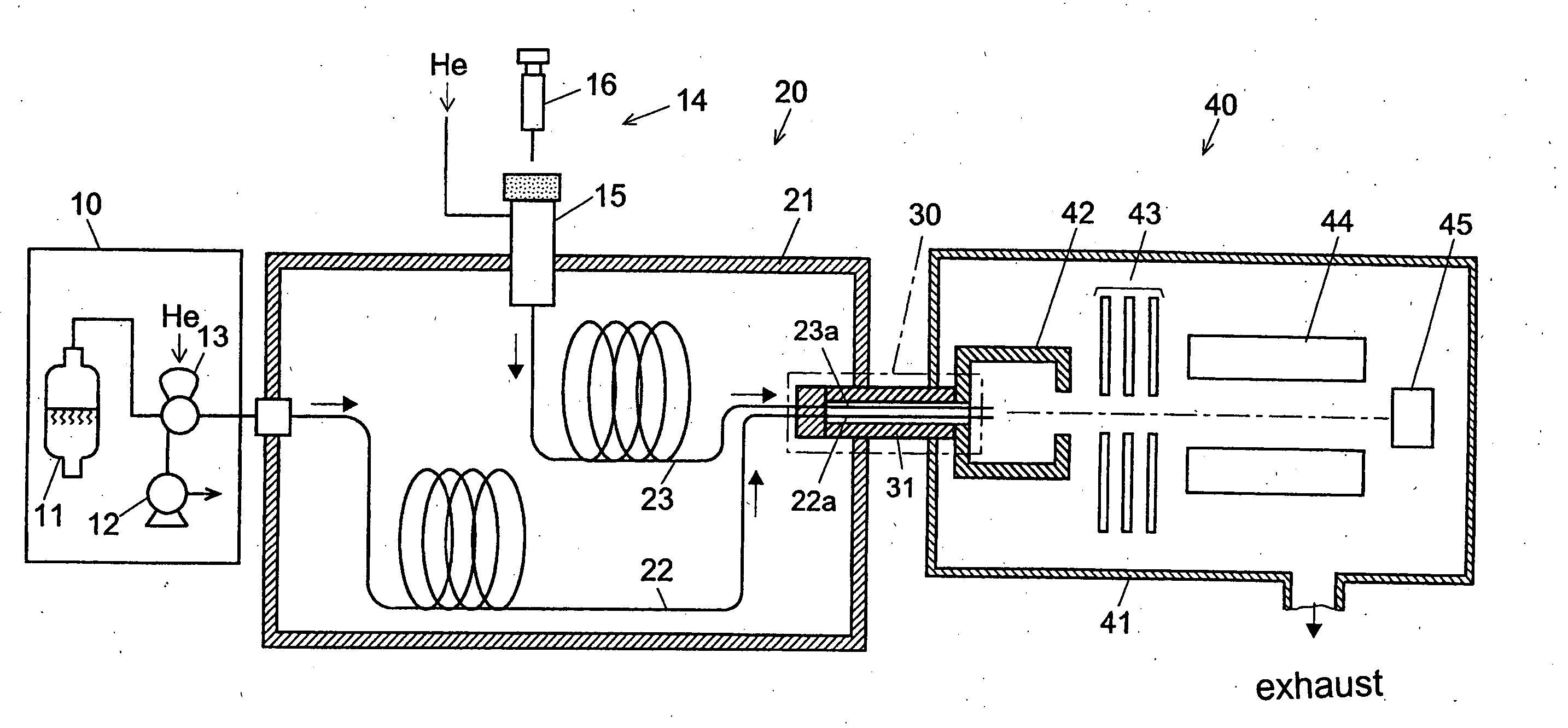
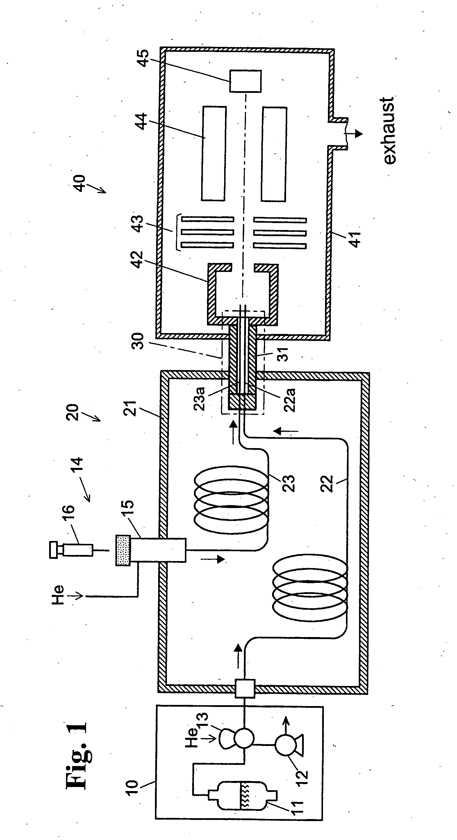
[0028]FIG. 1 is a schematic diagram of the components of a GC / MS system according to one embodiment of the present invention. In a GC (gas chromatography) part 20, two first and second capillary columns (below, simply described as “columns”) 22, 23 are located inside a column oven 21. The inlet end of the first column 22 is connected to a headspace sample introduction device 10, and the inlet end of the second column 23 is connected to a splitless type sample gasification chamber 15 of a liquid sample introduction device 14.

[0029] The headspace sample introduction device 10 includes a container 11 for storing a liquid sample, a pump 12 for aspirating a sample gas, an aspiration retention part 13 for retaining a fixed quantity of sample gas aspirated from the headspace inside the container 11. At times other than when the ...


PUM


Abstract

A gas chromatography/mass spectrometry system includes two sample introduction parts, a gas chromatography part having two columns, a column oven for housing the two columns in a parallel configuration, an interface part through which an outlet end of each of the two columns is inserted, and a mass spectrometry part. The mass spectrometry part has an ionization chamber to which the outlet ends of the columns inserted through the interface part are connected, a mass separation part, an ion detector, and a vacuum chamber for housing the ionization chamber, the mass separation part, and the detector. Because the outlet ends of the parallel columns are both connected to the ionization chamber, the carrier gas flow and line velocity are the same as though there is one column, thereby avoiding line stagnation. Since analyses can be performed selectively with a single system, results having high reliability and precision can be obtained.

Description

BACKGROUND OF THE INVENTION AND RELATED ART STATEMENT [0001] The present invention relates to a gas chromatography / mass spectrometry system that includes a gas chromatograph and a mass spectrometer. [0002] Recently, gas chromatography / mass spectrometry systems (“GC / MS”) combining gas chromatographs and mass spectrometers have been widely used for identification analysis and quantification analysis of various kinds of samples. See, for example, the system disclosed in Japanese Unexamined Patent Publication No. H10-283982. [0003] In a GC / MS, when introducing sample gases into the column of the GC part, various kinds of sample introduction devices are used in accordance with the types and properties of the samples. For example, when analyzing agricultural chemicals, and in environmental analyses, a liquid sample introduction device is used which gasifies the liquefied sample inside a high-temperature sample gasification chamber and sends it into the column. [0004] Also, when analyzing ...

Claims


Application Information

Patent Timeline
IPC IPC(8): G01N30/02
CPCG01N30/466G01N30/7206G01N2030/3084
Inventor MIYAGAWA, HARUHIKO
Owner SHIMADZU CORP
Why Eureka
Try Eureka