Method of thermal adherend release and apparatus for thermal adherend release

a technology of thermal adherends and adhesives, which is applied in the direction of film/foil adhesives, chemistry apparatus and processes, layered products, etc., can solve the problems of difficult uniform shrinkage of the base material in the machine direction and the transverse direction, the difficulty of reducing the adhesive strength between the diced semiconductor chip and the base material, and the breakage of the semiconductor chip, etc., to suppress or prevent the generation of inconveniences, the effect of simple and rapid separation

Inactive Publication Date: 2006-06-15
NITTO DENKO CORP
View PDF2 Cites 29 Cited by
  • Summary
  • Abstract
  • Description
  • Claims
  • Application Information

AI Technical Summary

Benefits of technology

[0021] According to the thermal release method of an adherend of the invention, in releasing an adherend from a heat-peelable pressure-sensitive adhesive sheet, only a desired part of an adherend of plural adherends can be released simply and more rapidly, while the remainder can be kept in the state that it sticks to the heat-peelable pressure-sensitive adhesive sheet. Also, at the time of processing, the adherend can be held without causing falling off from a heat-peelable pressure-sensitive adhesive sheet, and after processing, a desired part of an adherend of plural adherends can be separated easily and more rapidly from the heat-peelable pressure-sensitive adhesive sheet without causing damaging or displacement of the adherend.
[0022] In consequence, according to the thermal release device of an adherend of the invention, in a finer and thin-layered adherend, at the time of processing, the adherend can be well held without causing release, and after processing, only a desired part of an adherend of plural adherends can be released with good precision simply and rapidly. Therefore, it is possible to suppress or prevent the generation of inconveniences in the adherend such as damaging and displacement, thereby enabling one to effectively prevent a lowering in productivity or yield, or the like.

Problems solved by technology

However, only by this method for shrinking a base material, it is difficult to reduce an adhesive strength between the diced semiconductor chip and the base material to an extent that the semiconductor chip can be easily picked up.
Also, in shrinking, it is difficult to uniformly shrink the base material in the machine direction and the transverse direction.
Thus, there was a problem that the semiconductor chip causes displacement and comes into contact with an adjacent semiconductor chip, resulting in breakage of the semiconductor chip.
At this time, deformation or falling off of other cut pieces was found to occur due to vibration as generated at the time of transferring and separating the cut piece of a part of the parts.
Furthermore, in a dicing step of a semiconductor wafer or a laminated capacitor, after the dicing processing, in heating the heat-peelable pressure-sensitive adhesive sheet holding the parts to release the parts, there were involved such problems that the whole of the parts including the parts which one intends to hold is separated and that displacement or falling off of the parts occurs due to vibration as generated at the time of transferring and separating the parts after processing.

Method used


Image

  • Method of thermal adherend release and apparatus for thermal adherend release
  • Method of thermal adherend release and apparatus for thermal adherend release

Examples


example 1

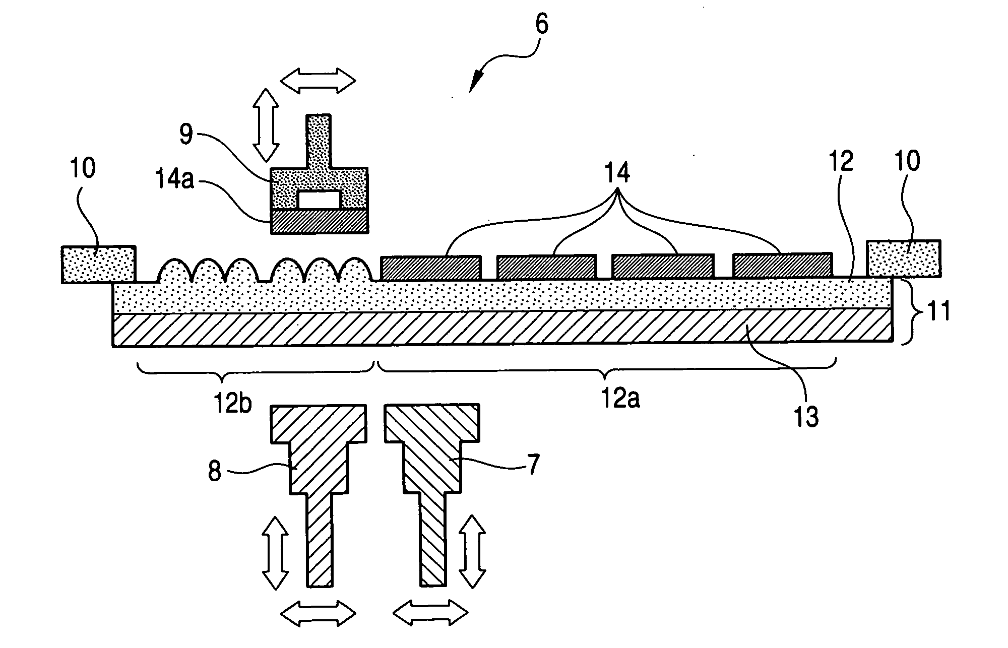
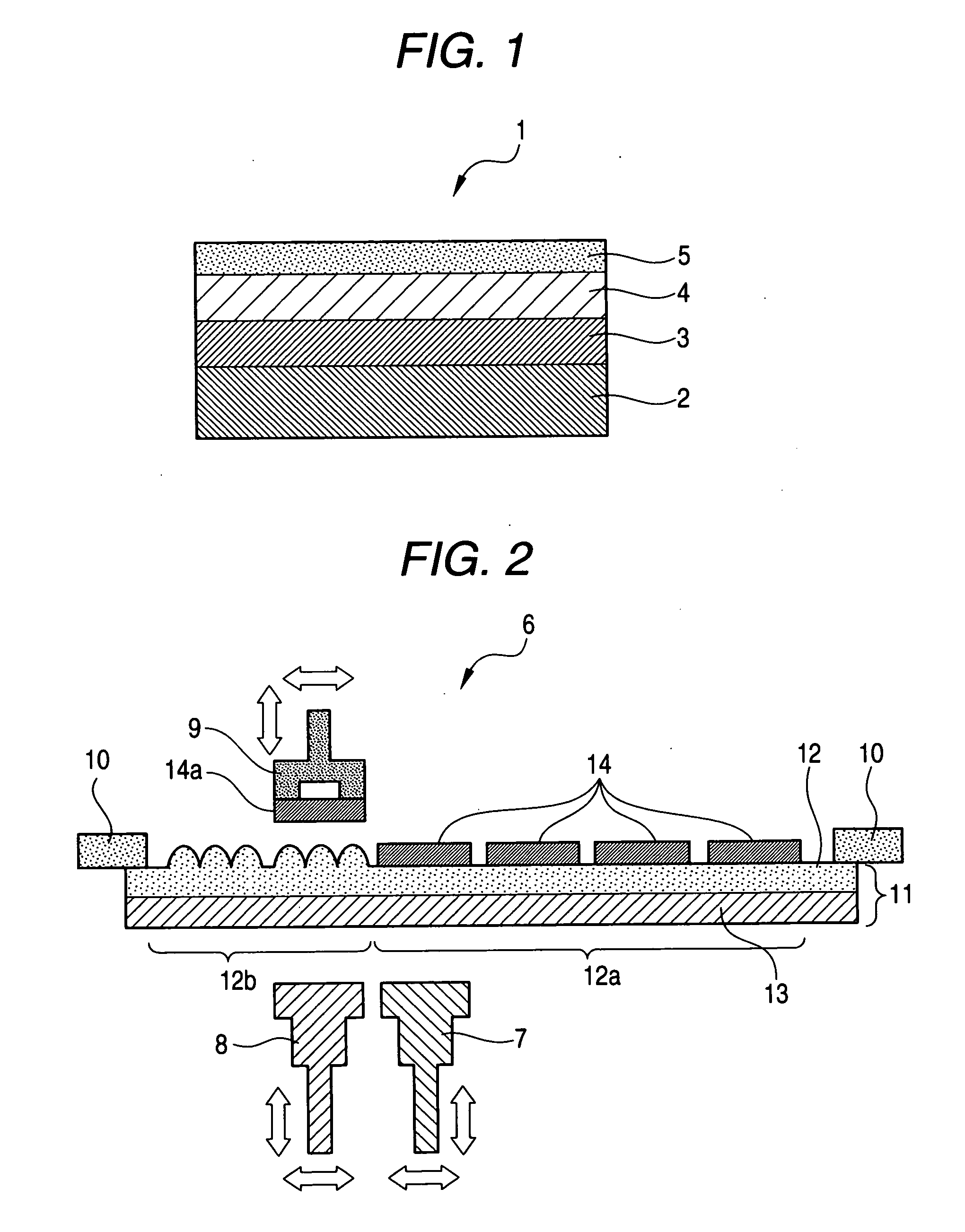
[0135] In a thermal release type pressure sensitive adhesive tape (fixed by a fixing ring) constructed of a polyester base material (100 μm in thickness) and a heat-expandable pressure-sensitive adhesive layer, whose adhesive strength is lowered at 90° C. (the release start temperature is 90° C.), as formed on one surface of the polyester based material, a silicon wafer (150 μm in thickness) having a diameter of 6 inches was stuck on the surface of the heat-expandable pressure-sensitive adhesive layer without incorporation with air bubbles. Thereafter, the foregoing silicon wafer was diced into a size of 3 mm in square.

[0136] Also, a pre-heating section and a release and heating section in which a stainless steel (SUS 304) plate having a size of 3 mm in square and a thickness of 2 mm and a thermally conductive rubber sheet (3 mm in square and 1 mm in thickness) were provided in a tip of an electric heater were respectively prepared as the pre-heating section and the release and hea...

example 2

[0139] A cut piece of a silicon wafer was released in the same manner as in Example 1, except for using a thermal release type pressure sensitive adhesive tape having a heat-expandable pressure-sensitive adhesive layer having a release start temperature of 120° C. as the thermal release type pressure sensitive adhesive tape and employing the conditions such that the temperature of the rubber sheet part (leading-tip part) in the pre-heating section was 105° C. and that the temperature of the rubber sheet part (leading-tip part) in the release and heating section was 170° C. On this occasion, when the cut piece of the silicon wafer was adsorbed by the adsorption nozzle and released, a time required for releasing one cut piece of the silicon wafer (time required for release in average) was 1.5 seconds as shown in Table 1.


PUM

PropertyMeasurementUnit
temperatureaaaaaaaaaa
mean particle sizeaaaaaaaaaa

Abstract

A method of thermal adherend release, wherein a part of adherends adherent to a heat-peelable pressure-sensitive adhesive sheet having a heat-expandable layer containing a foaming agent are selectively released from the pressure-sensitive adhesive sheet by partly heating the heat-peelable pressure-sensitive adhesive sheet, wherein the method comprises previously heating a sticking site of an adherend to be released at a temperature at which the heat-expandable layer of the heat-peelable pressure-sensitive adhesive sheet does not expand and then heating the sticking site of the adherend in the heat-peelable pressure-sensitive adhesive sheet at a temperature at which the heat-expandable layer expands to thereby selectively releasing the adherend.

Description

FIELD OF THE INVENTION [0001] The present invention relates to a method for selectively releasing a part of an adherend from a heat-peelable pressure-sensitive adhesive sheet provided with a heat-expandable layer by heating and to an apparatus for thermal adherend release to be used by the subject method. BACKGROUND ART [0002] As a method for releasing the parts as stuck to a pressure-sensitive adhesive tape from the pressure-sensitive adhesive tape after processing, for example, there is a method for picking up a semiconductor chip as prepared by shrinking a base material and dicing it (see Patent Document 1). However, only by this method for shrinking a base material, it is difficult to reduce an adhesive strength between the diced semiconductor chip and the base material to an extent that the semiconductor chip can be easily picked up. Also, in shrinking, it is difficult to uniformly shrink the base material in the machine direction and the transverse direction. Thus, there was a...

Claims


Application Information

Patent Timeline
Patent Type & Authority Applications(United States)
IPC IPC(8): B29C63/00C09J5/00B32B37/00C09J7/38
CPCB29C63/0013C09J7/0207C09J2203/326C09J2205/11C09J2205/302Y10S438/976H01L2221/68327H01L2924/19041Y10T156/1911Y10T156/1153Y10T156/1147H01L21/6836C09J7/38C09J2301/412C09J2301/502H01L21/82H01L21/78
Inventor DOI, TOMOKOSHIMOKAWA, DAISUKEARIMITSU, YUKIO
Owner NITTO DENKO CORP
Why Eureka
Try Eureka