
Bit depth reduction for analog to digital conversion in global positioning system

a global positioning system and converter technology, applied in the direction of direction finders, radio wave direction/deviation determination systems, instruments, etc., can solve the problems of low signal strength, gps system to provide false and inaccurate positioning data, and adverse effects on gps signals, so as to reduce the requirement of bit depth. , the effect of reducing the requirement of a/d converter

Inactive Publication Date: 2006-06-15
THE JOHN HOPKINS UNIV SCHOOL OF MEDICINE
View PDF14 Cites 8 Cited by
  • Summary
  • Abstract
  • Description
  • Claims
  • Application Information

AI Technical Summary

Benefits of technology

[0014] It is, therefore, an aspect of the present invention to provide a system for reducing a bit-depth requirement for an A / D converter in a GPS receiver.
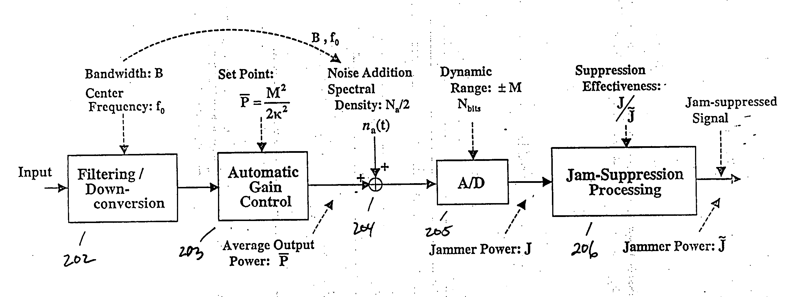
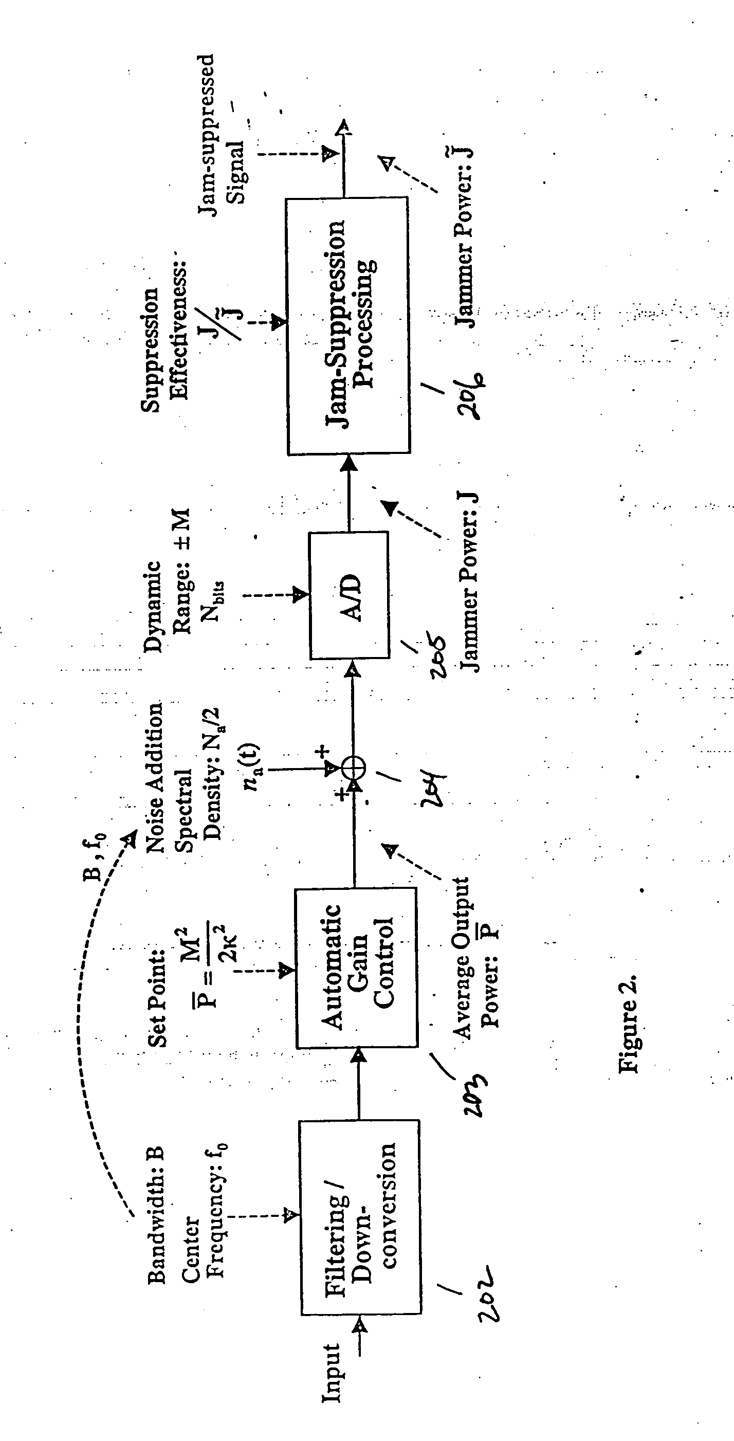
[0016] The foregoing aspects of the present invention are realized by a system for reducing a bit-depth requirement for an A / D converter in a GPS receiver having an antenna for receiving an analog input signal and a low noise amplifier for amplifying the input signal, comprising a filter for filtering about a bandwidth B the amplified signal; a down-conversion module centering the frequency of the filtered signal about a center frequency f0; an automatic gain controller (AGC) for controlling the gain of the down-converted signal to one of maximize the dynamic range of the system and minimize clipping of down-converted signal; an adder for adding noise to the gain controlled signal, said noise based upon the bandwidth B, center frequency f0, and a spectral density Na / 2; and an analog to digital (A / D) converter for converting the added noise signal to a digital signal, wherein the noise added to the gain controlled signal reduces the bit depth requirement of the A / D converter.

Problems solved by technology

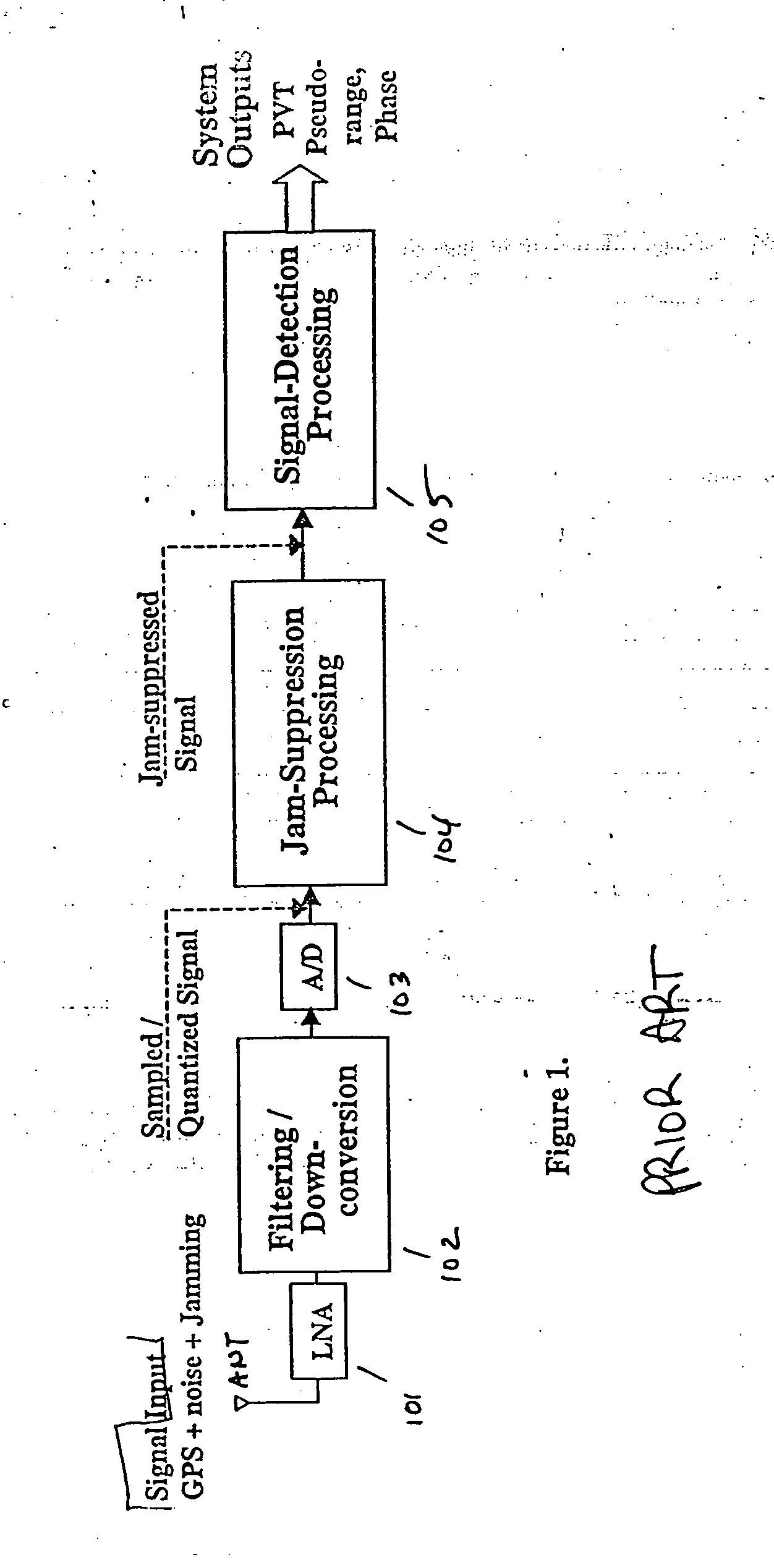
GPS signals can be adversely affected by various factors including, for example, low signal strength, noise and GPS jamming devices.
Each of these causes the GPS system to provide false and inaccurate positioning data in the particular applications.
In turn, this inaccurate or false data can cause devastating effects.
The combination of these requirements presents major challenges to A / D technology in linearity, speed, resolution, and power consumption.
Particularly troubling jamming systems are those in which a highly correlated jamming signal is used to jam the GPS signal.

Method used


Image

  • Bit depth reduction for analog to digital conversion in global positioning system
  • Bit depth reduction for analog to digital conversion in global positioning system
  • Bit depth reduction for analog to digital conversion in global positioning system

Examples


example i

[0043] As a first example, for the case where J / {tilde over (J)}=50 dB and K=2.628, the loss factor computed for Nbits=12 is 0.662 dB for narrow band, and 1.237 dB for wide band jammers. The numerically evaluated loss for the pure tone jammer is ˜3 dB. Identical wide and narrow band losses are achieved at Nbits=10 for J / {tilde over (J)}=38 dB, and at Nbits=8 for J / {tilde over (J)}=26 dB. For these cases, the loss factor attains its maximum value at a J / S power ratio ˜90 dB, 78 dB, and 66 dB, respectively. Beyond these limits, the loss factors are unaffected by further increases in jamming level. In particular, these loss values apply at the specified bit depths at the current military requirement of J / S power ratio=120 dB and beyond.

example ii

[0044] As another example, a baseline case expressing the capabilities of the system is the case where K=2.628, Nbits=12, J / {tilde over (J)}=50 dB, with σa=LSB. The narrow band jammer loss=0.662 dB for all jamming levels having a J / S power ratio of 90 dB and beyond (i.e. including 120 db), and is less for all jamming levels below 90 dB. The key point is that application of the system according to the present invention reduces the word length of the A / D converter 205 by 4-5 bits, which translates into a factor of 16 to 32 in resolution / linearity requirements, while only realizing a loss factor of ˜1.2 to 2 dB in the worst case. Application of the system thus represents a huge technology simplification for A / D converters in a GPS system.

example iii

[0045] In the case of a pure tone jammer, the jammer signal is represented by Equation B-1

J(t)=AJ cos(2πfJt+2J)  (B-1).

The jammer power is represented by Equation B-2

J=AJ2 / 2  (B-2).

The full received input signal is the GPS signal plus noise n(t) plus the jammer signal J(t), and the objective is to keep the jammer from seizing control of the A / D converter. The input signal is represented by Equation B-3

r(t)=Ap(t)cos(2πfct+θs)+n(t)+J(t)  (B-3)

where n(t) is band limited noise of spectral density No / 2 in the system passband.

[0046] A down-converter and low-pass filter of bandwidth B processes the input signal. The A / D converter operation occurs after down conversion and low-pass filtering. Multiplication by the local code and summation produces the I and Q summation values passed to subsequent processing. Determining the number of bits Nbits for the A / D converter proceeds as follows.

[0047] First quantizing to the noise level is required. Specifically, there will be quantities ...


PUM


Abstract

Disclosed is a system and method for reducing a bit-depth requirement for an A / D converter in a GPS receiver having an antenna for receiving an analog input signal and a low noise amplifier for amplifying the input signal, comprising a filter for filtering about a bandwidth B the amplified signal; a down-conversion module centering the frequency of the filtered signal about a center frequency f0; an automatic gain controller (AGC) for setting a set point of the input signal; an adder for adding noise to the gain controlled signal, said noise based upon the bandwidth B and center frequency f0; and an analog to digital (A / D) converter for converting the added noise signal to a digital signal, wherein the noise added to the gain controlled signal reduces the bit depth requirement of the A / D converter.

Description

CROSS-REFERENCE TO RELATED APPLICATIONS [0001] This application claims the benefit of U.S. Provisional Application No. 60 / 376,724, filed Apr. 30, 2002, the contents of which are incorporated herein by reference.STATEMENT OF GOVERNMENTAL INTEREST [0002] This invention was made with Government support under Contract No. F29601-00D-0244 awarded by the United States Air Force. The Government has certain rights in the invention.BACKGROUND OF THE INVENTION [0003] 1. Field of the Invention [0004] The present invention relates generally to a system and method for an analog to digital (A / D) converter, and in particular, to a system and method for managing a bit-depth requirement for an A / D converter in a GPS receiver intended for operation in a high jamming environment. [0005] 2. Description of the Relation Art [0006] Global Positioning Systems (GPS) are widely utilized in both commercial and military applications. Whether determining the location of a cellular telephone having a GPS trackin...

Claims


Application Information

Patent Timeline
Patent Type & Authority Applications(United States)
IPC IPC(8): G01S3/16G01S5/14G01S19/21
CPCG01S19/21G01S19/37
Inventor HENDERSON, ROBERT L.ASHER, MARK A.
Owner THE JOHN HOPKINS UNIV SCHOOL OF MEDICINE
Learn More