Radio frequency tags for use in a motion tracking system

a radio frequency tag and motion tracking technology, applied in the field of motion capture, can solve the problems of inability to accurately identify the position of the object, the gps based system is relatively slow, and the types of applications for which the motion capture system is typically used, and the electromechanical system is often bulky and obtrusive, so as to reduce the manual correlating and manipulating of the cg image

Inactive Publication Date: 2006-06-15
MENACHE
View PDF69 Cites 137 Cited by
  • Summary
  • Abstract
  • Description
  • Claims
  • Application Information

AI Technical Summary

Benefits of technology

[0017] Once the position of the reference tag is determined relative to the sensors, digital samples from the sensors are processed to extract a pseudorange measurement between each tag and each sensor. The measurements are pseudoranges, as opposed to ranges, because they contain a time term as well as a distance term. These measurements are differenced between the marker tags and the reference tag, and the resulting single differences are differenced between sensors to form double differences. The double differences are processed to determine the marker tag positions at each measurement time relative to the reference tag position. Equivalently, the position of each of the marker tags can be determined relative to a locus within any frame of reference including each other, the sensors positions, or any arbitrary coordinate system, using known mathematical coordinate transformations. Because the algorithms used to process the signals from the reference tag and marker tags cause the clock-dependent terms to drop out, the positions of the marker tags can be determined to a very high degree of accuracy without requiring clocks to be synchronized between sensors, between tags, or between sensors and tags.
[0018] The signals transmitted by the tags are code sequences modulated on a carrier frequency and spread using direct-sequence spread-spectrum techniques. The code sequences include a synchronization code, which is common to all tags, and a tag identification code, which is unique to each tag. In a preferred embodiment the synchronization code is the 16-bit Neuman-Hoffman sync word OEED hex having good autocorrelation characteristics. The tag identification codes are chosen to minimize pairwise cross-correlation. Those codes are randomly chosen vectors in the binary extended quadratic residue code space. The processing system uses code phase and carrier phase determinations to resolve the positions of the tags to within a fraction of a wavelength. The transmitters transmit microbursts of code such that the transmitters are transmitting less than 5% of the time, less than 1% of the time, and in the exemplary embodiment approximately 0.2% of the time. This small duty cycle minimizes battery drain at the transmitters and reduces the likelihood of collisions. The transmission rate is preferably an integer multiple of both 24 per second and 30 per second, and more preferably 240 per second. This ensures that motion can be captured at a frame rate that is equal to either 24 frames per second or 30 frames per second, which are standard frame rates used within the entertainment industry.
[0023] In another aspect, the invention is of a match moving system which utilizes the RF motion capture system described to track movements of a motion picture camera and perform post-processing on the recorded moving picture image in accordance with the tracked position and attitude of the camera. In this aspect of the invention, at least three marker tags are placed on a motion picture camera such as a hand held motion picture camera. The marker tags are placed in non-planar positions on the camera such that the locations of the three tags completely determines the camera's spatial position as well as its pitch, yaw, and roll angles. The camera records a scene while the camera is moving, such as by being hand carried by the camera operator. Because the exact position and attitude of the camera is precisely recorded by the RF motion tracking system, the resulting image can later be post-processed to achieve a number of desirable effects.
[0024] In one example, the recorded scene can be post-processed to insert a digital computer generated image (CG) image into the scene. As the camera pans horizontally or vertically around the scene, moves forward or backwards, rotates, pitches, or performs any other motion, the CG image can be altered to match the motion of the camera. The appearance of the CG image changes exactly as one would expect an image of an object physically present in the scene to change as the camera moves. The result is a realistic CG image within a motion picture while substantially reducing manual correlating and manipulating of the CG image as was required in certain prior art systems. In another example, the match moving system allows the recorded image to be post-processed to remove camera jitter, that is, to remove from the recorded image the effects of small motions of the camera so that to the viewer the camera appears to have been held steady, although possibly moving, throughout the filming of the scene.

Problems solved by technology

Systems based on the Global Position System (GPS) and its array of satellites can also be used to track the positions of objects on the earth such as cargo containers, although GPS based systems are relatively slow, inaccurate, bulky, and expensive for the types of applications for which motion capture systems are typically used.
Optical motion tracking systems are limited to line-of-sight operation.
Electromechanical systems are often bulky and obtrusive, and are not well suited for tracking the relative movement of independent objects.

Method used


Image

  • Radio frequency tags for use in a motion tracking system
  • Radio frequency tags for use in a motion tracking system
  • Radio frequency tags for use in a motion tracking system

Examples


embodiment

First Exemplary System Embodiment

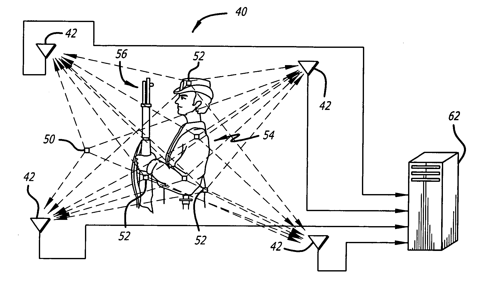
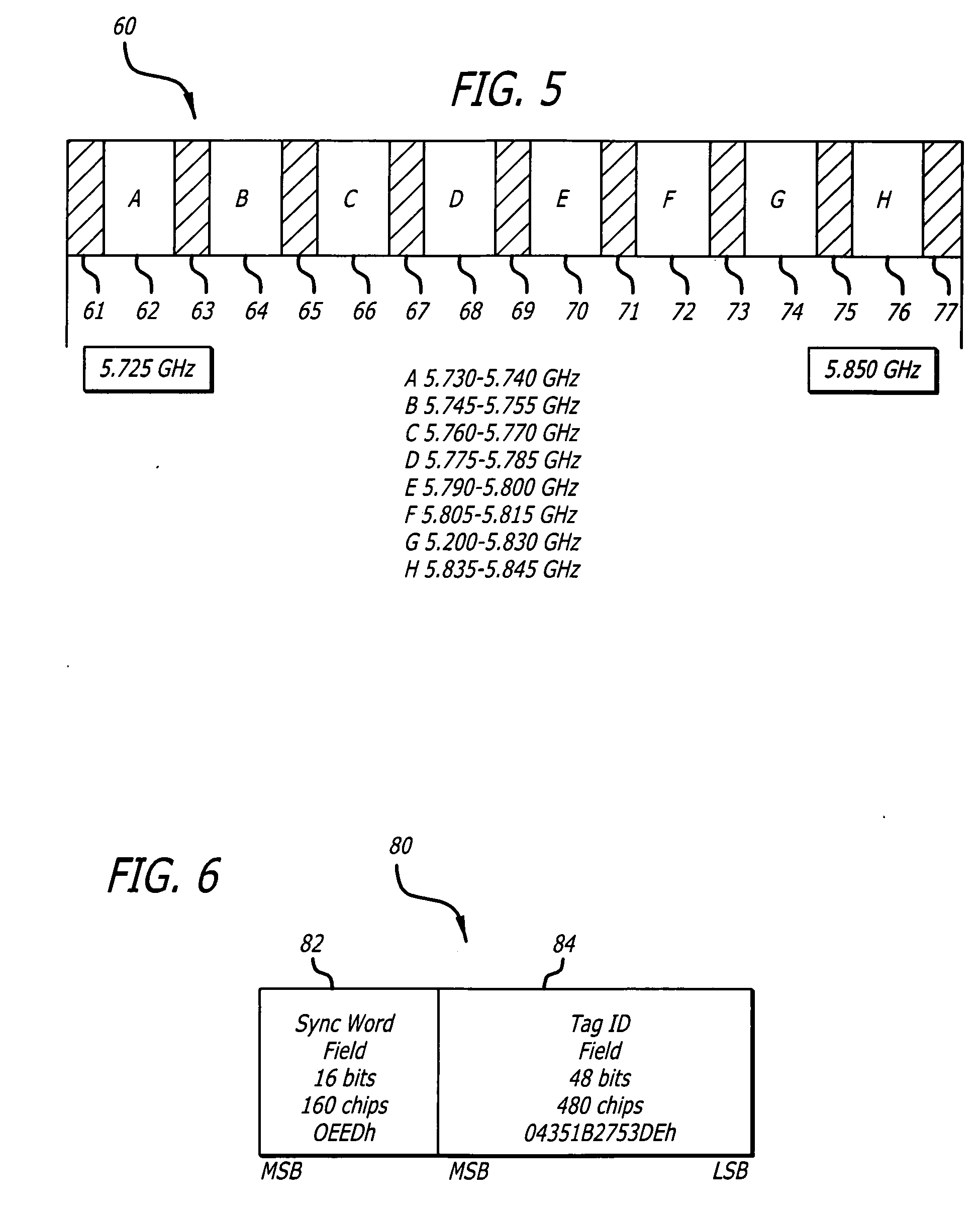
[0096] In a first exemplary system embodiment, tags 50 and 52 transmit direct-sequence spread-spectrum microwave signal bursts. Sensors 42 down-convert and analog-to-digital (AID) sample the received signal band. Digital samples from sensors 42 are processed to extract code pseudorange and carrier pseudorange measurements for each of the tags 50 and 52. These pseudorange measurements are processed to determine the tag positions at each sampling instant.

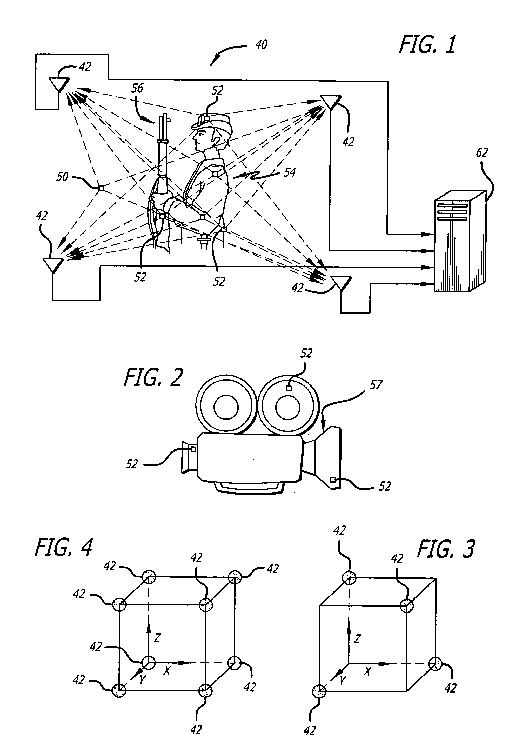
[0097] According to simulation results, the system is expected to operate with a capture zone of 130 m×55 m×10 m and can capture the positions of tags 52 anywhere within the zone. The minimum preferred sensor configuration is 8 sensors, one each near each of the vertices of the capture zone. Up to an additional 24 sensors placed around the periphery of the capture zone provide enhanced performance. Sensors 42 are setback such that there is approximately 5 to 15 meters between the front of a sensor and...

second system embodiment

[0202] A second system embodiment is similar to the first system embodiment, but uses some different techniques. The second system embodiment has generally been determined to be slightly preferred over the first system embodiment and is therefore considered to be a second generation design.

[0203] The capture zone is a rectangular parallelepiped with maximum diagonal up to 150 meters. The system captures tag positions anywhere within this capture zone. The system operates with any number of sensors 42 from 4 to 32. The sensors are placed such that the distance between the front of a sensor and the capture zone is between 5 percent and 15 percent of the maximum diagonal of the capture zone.

[0204] The buffer zone for each sensor is the volume defined by a plane tangent to the capture zone at its closest point to that sensor and a parallel plane twice the setback distance of that sensor away from the capture zone. Tags are excluded from the buffer zone. The system is capable of captur...


PUM


Abstract

Small radio frequency tags for use in a motion capture system include a power source, circuitry for generating radio frequency identification signals, an antenna for transmitting the signals, and means for automatically activating the tags so that the tags begin transmitting the signals including a tag identification code when a cover is removed. The activation means may include a release strip that, when removed, opens or closes an electrical circuit that activates the tag and also exposes an adhesive covered surface of the tag so that the tag can then be adhered to a clothed or unclothed human body or other object to be tracked. The activation means can also include an optical sensor, an oxygen sensor, or other sensors. The battery and the antenna may be printed or constructed of film, thus allowing the tag to be small, thin, and flexible.

Description

CROSS-REFERENCE TO RELATED APPLICATIONS [0001] This application is a divisional of U.S. application Ser. No. 10 / 777,414, now U.S. Pat. No. ______, which is a continuation-in-part of U.S. application Ser. No. 10 / 386,586 filed Mar. 11, 2003, now U.S. Pat. No. 6,831,603.BACKGROUND OF THE INVENTION [0002] 1. Field of the Invention [0003] This invention relates to the field of motion capture. More particularly, this invention relates to the field of a radio frequency (RF) tags for use in a position determining system. [0004] 2. Description of Related Art [0005] The term motion capture or motion tracking refers to tracking one or more objects or positions on an object or objects, and quantizing and recording the objects' positions as they move through space. The space can be 1-dimensional, 2-dimensional, or more commonly, 3-dimensional space. In many applications such as gait analysis a number of points on the object are to be tracked so as to effectively track, quantize, and record the l...

Claims


Application Information

Patent Timeline
Patent Type & Authority Applications(United States)
IPC IPC(8): G01S3/02G08B13/14G01S19/11G01S5/02G01S5/14G01S19/09H03M13/00H04L7/04
CPCA63F13/06A63F2300/1012A63F2300/6045Y10T156/10G01S5/06G01S5/14G01S5/0247A63F13/216A63F2300/5573A63F13/42A63F2300/8082A63F2300/306A63F13/525A63F13/5372A63F13/212A63F13/235A63F2300/6661A63F2300/1031A63F2300/205A63F13/23A63F13/213
Inventor MENACHE, ALBERTOSTURZA, MARK ALAN
Owner MENACHE
Why Eureka
Try Eureka