Optical unit and pojection type image display unit using it

a projection-type image and optical unit technology, applied in optics, projectors, instruments, etc., can solve the problems of inability to obtain a sufficient brightness, low light utilization efficiency, and dust adhering to the surface so as to reduce the reflections on the boundary surfaces, shorten the optical length of the optical path, and prevent dust adhering to the surface.

Inactive Publication Date: 2006-06-15
HITACHI LTD
View PDF6 Cites 9 Cited by
  • Summary
  • Abstract
  • Description
  • Claims
  • Application Information

AI Technical Summary

Benefits of technology

[0016] The reflection-type polarization plate reflects the light polarized to be parallel to the grating direction while transmitting the light polarized to be perpendicular to that, however, actually, it also transmits the light polarized to be parallel to the grating direction, but a very small amount thereof, and it also reflects the light polarized to be perpendicular to the grating direction, but a very small amount thereof; thereby lowering or reducing the contrast. Then, the auxiliary polarizers 91, 92 and 93 are provided at the inlet side while the auxiliary analyzers 121, 122 and 123 are at the exit side, so as to lessen the leakage lights when displaying the block; thereby obtaining an optical unit being favorable on the performance of contrast.
[0020] Also, a high resolution is demanded for enabling or dealing with HD (i.e., a high definition) of the apparatus, and so on, and because of this, each of the pixels on the liquid crystal panel also comes to be small in the size thereof. For example, in the case of the panel of 0.7 inch WXGA (1,368×768) on a mainstream of the products, the pixel pitch is about 15 μm, for example, but in the case of the panel of the same size, i.e., 0.7 inch, enabling 1080HD (1,920×1,080), the pixel pitch is about 8 μm, i.e., about a half thereof. Also an allowable value (hereinafter, being called “convergence shift”) comes to be about a half, in the positional gap of the each reflection-type liquid crystal panel 111, 112 or 113. On the other hand, so as to increase an output of a lamp and further to obtain high efficiency of a lightening optical system thereof, for the purpose of achieving the high brightness of the apparatus, the light energy irradiated upon the panels also comes up to be large, and also an increase of temperature comes to be large. When the temperature rises up, holder members for holding the reflection-type liquid crystal panel 111, 112 and 113 expand thermally, to shift the position of each of the reflection-type liquid crystal panel 111, 112 and 113; thereby, bringing about a problem that the convergence gap is generated, easily.
[0025] In this manner, the said optical units (i.e., the auxiliary analyzer, the reflection-type polarizing plate, reflection-type liquid crystal panels, the auxiliary analyzer, and the color separation means) are disposed within said hermetically sealed space; therefore, it is possible to preventing dust from adhering thereon. Also, said hermetically sealed space is filled up with the translucent liquid, having refraction index being small in the difference between said optical parts; therefore, it is possible to shorten an optical length of the optical path from said reflection-type image display element through said reflection-type polarization plate to said color separation means, comparing to that in the case of a medium of an air, thereby enabling small-sizing of said projection lens. And, it is also possible to reduce the reflections upon the boundary surfaces of said optical parts; therefore, there is no necessity of treating an anti reflection upon said optical parts, so that the cost can be lowered down. Further, said translucent liquid also functions as a cooling medium therein; therefore, it is possible to reduce the convergence shift. And further, it is possible to remove a fan for cooling or to lower the rotational speed thereof; therefore, the noises generated by the fan can be reduced.

Problems solved by technology

Though applying a color wheel as a means for displaying a color image in the Non-Patent Document 1 mentioned above, however in this case, a loss in an amount of light when it passes through the color wheel comes up to about ⅔; i.e., being low in an efficiency of utilizing light, and therefore, it is impossible to obtain a sufficient brightness, unless applying a lamp of a high output therein.
Further, it cannot said that the contrast is sufficient enough, and therefore, there is a necessity of further improvement thereof.

Method used


Image

  • Optical unit and pojection type image display unit using it
  • Optical unit and pojection type image display unit using it
  • Optical unit and pojection type image display unit using it

Examples


first embodiment

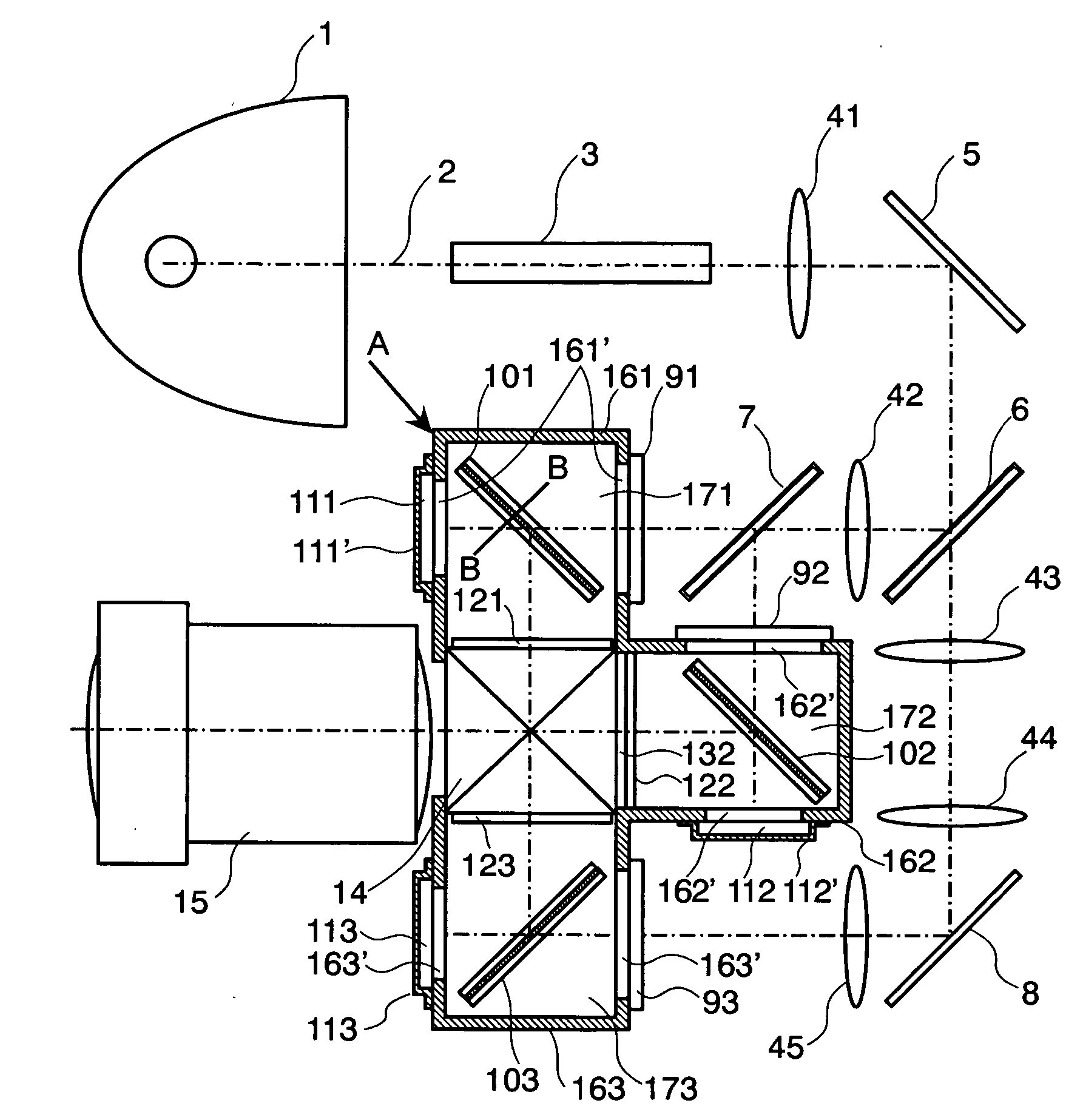
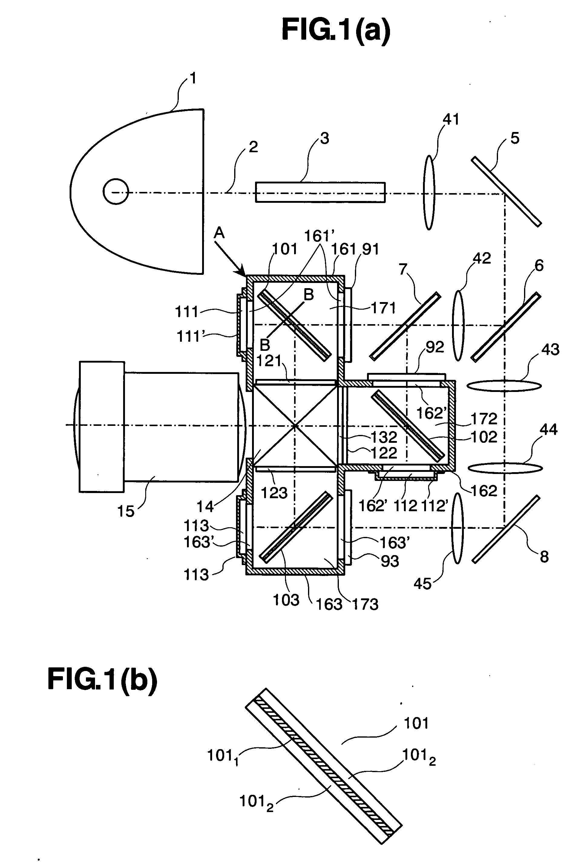
[0036] FIGS. 1(a) and 1(b) are views for showing an optical unit and a part thereof, according to the present invention, and FIG. 2 is a side view of an optical chassis portion shown in FIG. 1(a). However, FIG. 1(a) is a plane view of the optical unit, and FIG. 1(b) an enlarged structure view of a reflection-type polarization plate. Further, in those FIGS. 1(a) and 1(b) and FIG. 2, elements having the same functions to those shown in FIG. 8 mentioned above are attached with the same reference numerals thereof, and therefore the explanations thereabout will be omitted herein.

[0037] In those FIGS. 1(a) and 1(b) and FIG. 2, reference numerals 161, 162 and 163 depict a R-use optical chassis, a G-use optical chassis and a B-use optical chassis, respectively; 101, 102 and 103 a R-use reflection-type polarization plate, a G-use reflection-type polarization plate and a B-use reflection-type polarization plate, respectively, each applying a refraction grating therein; and further 171, 172 an...

second embodiment

[0064] Next, explanation will be made on a second embodiment according to the present invention.

[0065]FIG. 4 is a view for showing the optical unit according to the second embodiment of the present invention. In this FIG. 4, a reference numeral 16 depicts the optical chassis, and 17 the translucent liquid. However, in this FIG. 4, the elements having the functions same or similar to those shown in FIGS. 1(a) and 1(b) are attached with the same numeral references, and the explanation thereof is omitted herein. And, since the arrangement of the optical parts in this figure is also same to that of the first embodiment shown in FIGS. 1(a) and 1(b), and therefore the optical performances obtained therefrom are same to those; thereby omitting the explanation thereof. The description will not be made on effects thereof, but only new ones.

[0066] With this second embodiment according to the present invention, as is shown in FIG. 4, although being same to the first embodiment shown in FIGS. ...

third embodiment

[0069] Next, explanation will be made about a third embodiment according to the present invention.

[0070]FIG. 5 is a view for showing the optical unit according to the third embodiment of the present invention. In this FIG. 5, a reference numeral 216 depicts an optical chassis. However, the elements having the functions same or similar to those shown in FIGS. 1(a) and 1(b) are attached with the same numeral references, and the explanation thereof is omitted herein.

[0071] With this third embodiment, as shown in FIG. 5, changes are made on the arrangement of the R-use reflection-type liquid crystal panel 111, the G-use reflection-type liquid crystal panel 112 and the B-use reflection-type liquid crystal panel 113 in the second embodiment, so that they are in parallel with an incident surface of the cross dichroic prism, upon which the reflection light reflected upon each the liquid crystal panel is incident. Accordingly, differing from the first and second embodiments mentioned above,...


PUM


Abstract

An optical unit, comprising: a light source; a color separation means for separating a light emitted from the light source into plural pieces of color lights; reflection-type image display elements, upon each being incident the corresponding color of the lights from the color separation means, and for forming an optical image for each of the color lights, depending upon an image signal, with using polarization characteristics which the reflection-type image display elements have; and a color synthesizing means for synthesizing the optical images of the respective color lights, to be projected through a projection lens, enlargedly, and further comprising: a reflection-type polarization plate functioning as a polarization plate due to diffraction, being provided on an optical path extending from the color separation means to the reflection-type image display elements, to be a polarizer and an analyzer to the reflection-type image display elements; and an optical chassis for holding the reflection-type polarization plate and the reflection-type image display elements thereon, and having a translucent window on an incident light side of the reflection-type polarization plate while an exiting light side of the reflection-type polarization plate is sealed with an incident surface of the color synthesizing means, wherein a hermetically sealed space is defined by the optical chassis, the reflection-type image display elements and the incident surface of the color synthesizing means, and within the hermetically sealed space is disposed a translucent liquid having refraction index from 1.2 to 1.9.

Description

TECHNICAL FIELD [0001] The present invention relates to an optical unit and a projection-type image display apparatus using the same, in which a light emitted from a light source is incident upon a reflection-type image display element(s), thereby projecting the light which is / are reflected upon the said reflection-type image display element(s), enlargedly. BACKGROUND OF THE INVENTION [0002] Conventionally are already known a projection-type image display apparatus, which mounts an optical unit for modulating an intensity of light emitted from a light source through an image display element(s); i.e., the gradation is changed depending upon an image signal, thereby forming an optical image, and projecting that optical image, enlargedly, by means of a projection lens. And, as such the image display element, there are already known a transmitting-type liquid crystal panel, a reflection-type liquid crystal panel, and a micro mirror panel, and so on. [0003] Among of those mentioned above...

Claims


Application Information

Patent Timeline
Patent Type & Authority Applications(United States)
IPC IPC(8): G03B21/14G02B27/18G02B27/28G03B21/00
CPCG03B21/00G03B21/005
Inventor HIRATA, KOJINAKASHIMA, TSUTOMUYATSU, MASAHIKOMASUOKA, NOBUO
Owner HITACHI LTD
Why Eureka
Try Eureka