Failure localization in a transmission network

Active Publication Date: 2006-06-15
WSOU INVESTMENTS LLC
View PDF13 Cites 55 Cited by
  • Summary
  • Abstract
  • Description
  • Claims
  • Application Information

AI Technical Summary

Benefits of technology

[0012] This second aspect has the advantage that information about the fault location is also available for the “local” nodes along the path. The border node is thus able to perform an optimized, i.e., failure diverse, restoration.

Problems solved by technology

In particular, a failure adjacent network element detects the failure and activates a temporary tandem connection source function.

Method used


Image

  • Failure localization in a transmission network
  • Failure localization in a transmission network
  • Failure localization in a transmission network

Examples


Embodiment Construction

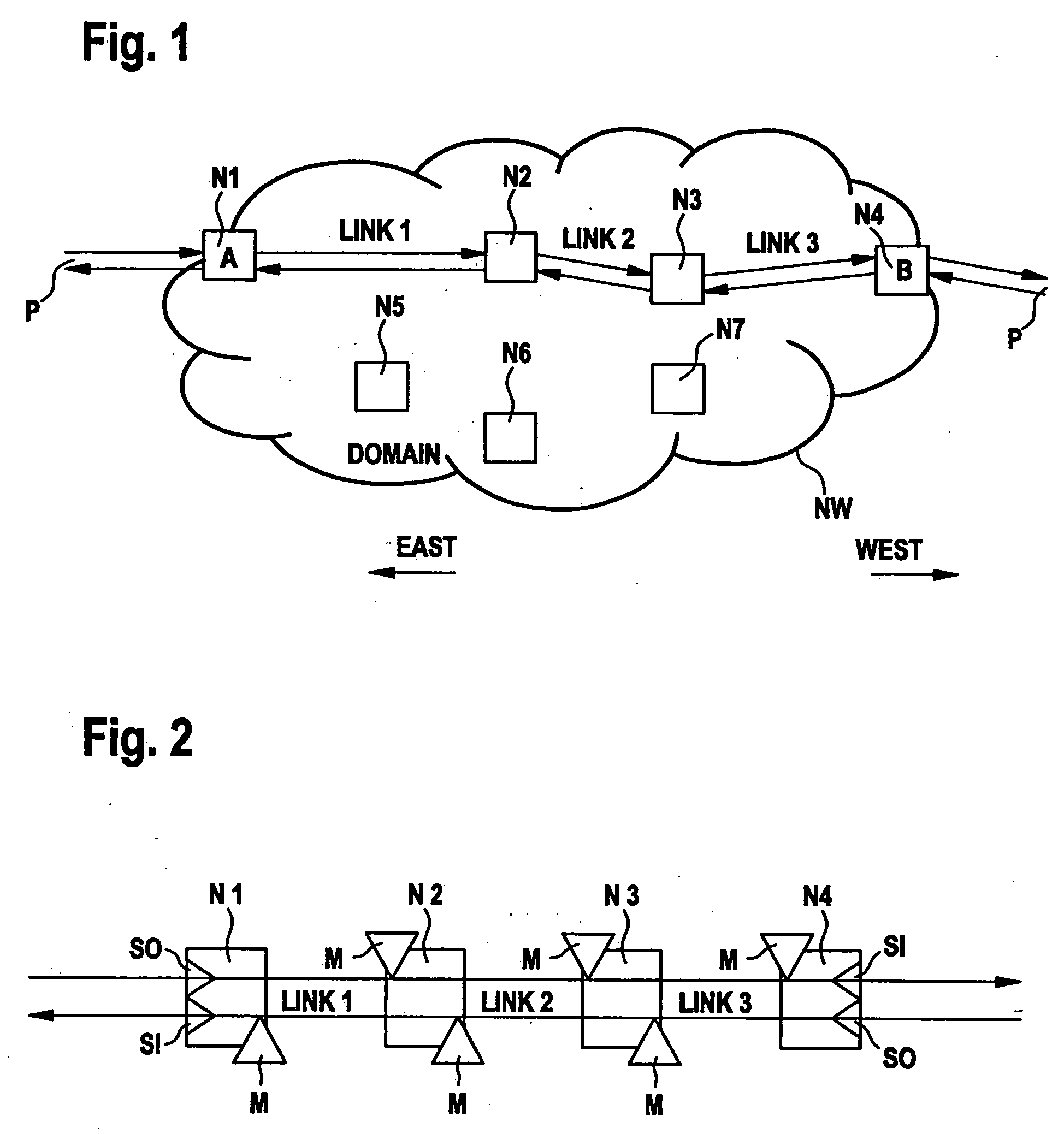
[0024]FIG. 1 shows a transmission network NW containing a number of network elements N1-N7. The network elements are physically interconnected in an arbitrary mesh structure, which is not shown in the example. Only links 1-3 interconnecting network elements N1, N2, N3, and N4, respectively, are shown in the figure. A logical connection (sometimes also referred to a sub-network connection) is established along these links, which carries a bi-directional path signal P. This path is used by way of example to demonstrate fault localization according to the invention.

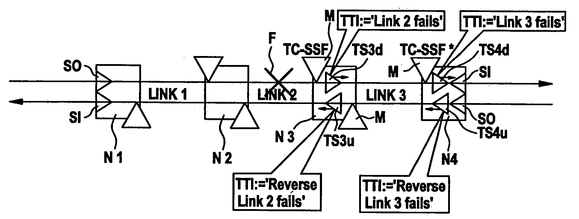
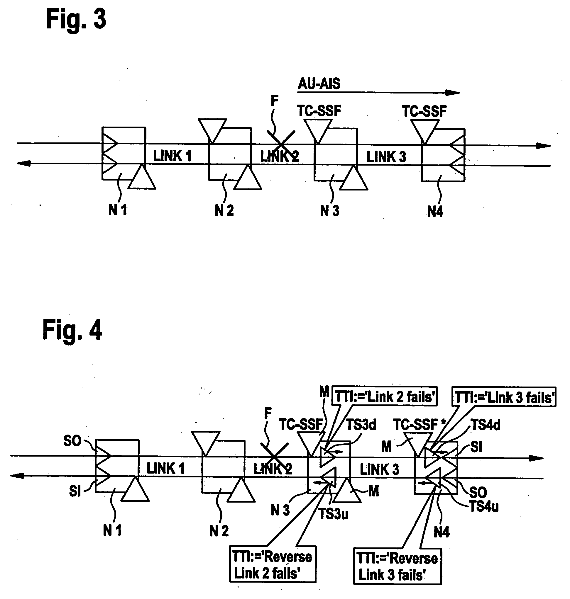
[0025] If the connection from N1 to N4 fails anywhere, subsequent network elements will typically create secondary alarm reports towards the network management plane, which then has to find out the exact location of the primary fault from all these alarms. In order to simplify this fault localization process, use is made of the tandem connection monitoring functions specified in ITU-T recommendations G.707 (SDH), G.709 (OTH...


PUM


Abstract

Failures are localized through the use of a Tandem Connection along a segment of a transmission path (P) to be monitored, non-intrusive intermediate Tandem Connection monitors (M), and temporary Tandem Connection sources created along the path segment in the case of a failure (F) in order to forward information about the fault location at least in downstream direction but preferably also in upstream direction. In particular, a failure adjacent network element (N3) detects the failure and activates a temporary tandem connection source function (TS3d, TS3u). This function creates a valid tandem connection signal and insert therein a failed link identifier (TTI). The network element (N4) terminating the tandem connection generates an alarm report including the failed link as indicated by the failed link identifier.

Description

[0001] The invention is based on a priority application EP 02 360 317.8 which is hereby incorporated by reference. FIELD OF THE INVENTION [0002] The present invention relates to the field of telecommunications and more particularly to a method and corresponding network devices for performing fault localization in a transmission network, preferably in an automatically switched optical network. BACKGROUND OF THE INVENTION [0003] Transmission networks serve for the transport of user signals, commonly referred to as tributary signals, in the form of multiplexed transmission signals. A transmission network consists of a number a physically interconnected network elements such as add / drop multiplexers, terminal multiplexers, and cross-connects. The physical interconnection between two network elements is referred to as a section or link while the route a particular tributary takes through the transmission network from end to end is known as a path. A path is represented by a multiplexing ...

Claims


Application Information

Patent Timeline
Patent Type & Authority Applications(United States)
IPC IPC(8): H04J3/14H04Q11/04
CPCH04J2203/006H04L41/0659H04L41/0677H04Q11/0478
Inventor HUCK, MARTINBELLER, DIETERANSORGE, STEFAN
Owner WSOU INVESTMENTS LLC
Why Eureka
Try Eureka