Pattern forming method and method of manufacturing ink jet recording head

a technology of ink jet recording head and pattern opening portion, which is applied in the direction of diazo-type processes, photomechanical equipment, instruments, etc., can solve the problems of difficult to keep the pattern opening portion in a sharp edge shape, difficult to control the edge shape of the pattern opening portion and the taper angle of the wall surface of the pattern recess, etc., and achieve high quality

Inactive Publication Date: 2006-06-15
CANON KK
View PDF14 Cites 12 Cited by
  • Summary
  • Abstract
  • Description
  • Claims
  • Application Information

AI Technical Summary

Benefits of technology

[0021] As an effect of the present invention, there can be provided a pattern forming method which can keep the edge of the opening portion of a pattern in a sharp state and yet, can make the wall surface of the recess of the pattern into a tapered shape. Further, when the present invention is applied to the manufacture of the ink discharge port of an ink jet recording head, an ink discharge port of which the edge of the opening portion is kept in a sharp state and the wall surface assumes a tapered shape becomes formable by a simple method. As a result, there can be provided an ink jet recording head which can obtain an image of high quality and a method of manufacturing the same.

Problems solved by technology

In the conventional method, however, it has been difficult to control the edge shape of a pattern opening portion and the taper angle of the wall surface of a pattern recess at a time.
That, if the focus (imaging position) of the pattern by an exposing machine is set near the surface of a coat resin layer formed of the photosensitive resin, there can be obtained an edge shape in which the pattern opening portion is sharp, but it has been difficult to make the wall surface of the pattern recess into a tapered shape.
Conversely, if the imaging position of the pattern by the exposing machine is offset (defocused) from the vicinity of the surface of the coat resin layer formed of the photosensitive resin, it becomes easy to make the wall surface of the pattern recess into a tapered shape, but it has been difficult to keep the pattern opening portion in a sharp edge shape.
In the pattern exposure in the defocused state, however, there has been a case where the edge of the distal end of the nozzle (the opening portion of the ink discharge port) deviates from a proper focus and therefore tend to become rounded, and this has not been preferable in the discharging characteristic of ink.

Method used


Image

  • Pattern forming method and method of manufacturing ink jet recording head
  • Pattern forming method and method of manufacturing ink jet recording head
  • Pattern forming method and method of manufacturing ink jet recording head

Examples


embodiment

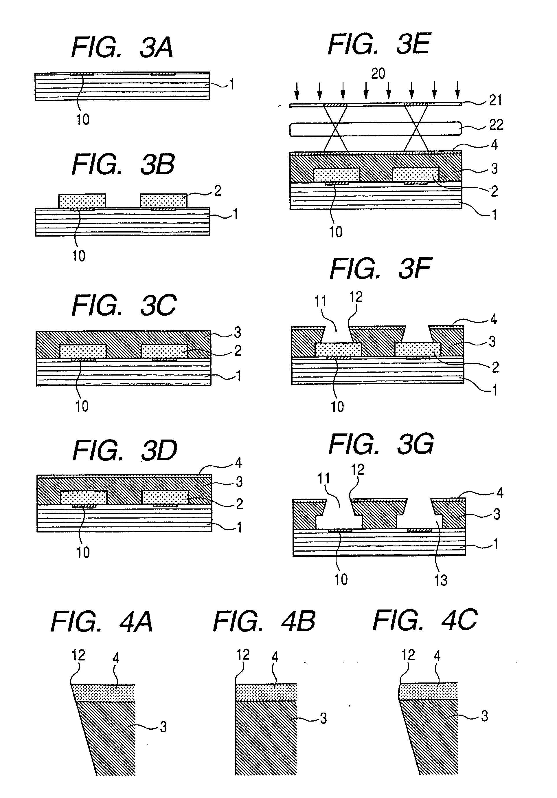
[0060] A more specific embodiment of the present invention will now be described. In this embodiment, an ink jet recording head was made in accordance with the procedure shown in FIGS. 3A to 3G.

[0061] First, as a soluble resin layer, polymethyl isopropenyl ketone (ODUR-1010(trade name) produced by, Tokyo Oka Kogyo Co. Ltd.) was applied onto an formed into film by spin coating on a silicon substrate on which an electro-thermal transducing element as an ink discharge pressure generating element is formed. Then, it was prefaced at 120° C. for 6 minutes, whereafter pattern exposure for forming a pattern providing an ink flow path was effected by a mask aligner UX3000 (trade name) produced by Ushio Denki Co., Ltd. The exposure was effected for 3 minutes, whereafter development was effected by the use of a mixed solvent of methyl isobutyl ketone (MIBK) / xylene=2 / 1 (mass ratio), and rinse was effected with xylene. The aforementioned polymethyl isopropenyl ketone is a so-called positive typ...


PUM

PropertyMeasurementUnit
temperatureaaaaaaaaaa
thicknessaaaaaaaaaa
taper angleaaaaaaaaaa

Abstract

The present invention has as its object to provide a pattern forming method which, even if a pattern is formed by photolithography, can keep the edge of the opening portion of the pattern in a sharp state and yet, can make the wall surface of the recess of the pattern into a tapered shape, and a method of manufacturing an ink jet recording head to which the aforedescribed method is applied. The pattern forming method is a pattern forming method having the step of forming on a substrate a coat resin layer containing a photopolymerizable resin, the step of applying a solution containing a photopolymerization starting agent onto the coat resin layer, and forming the distribution of the density of the photopolymerization starting agent in the direction of film thickness of the coat resin layer, and the step of applying light from above the coat resin layer through a mask having a pattern depicted thereon, and the step of developing the coat resin layer to which the light has been applied to thereby make it into a coat resin layer having the pattern, and this method is applied to the manufacture of an ink jet recording head.

Description

BACKGROUND OF THE INVENTION [0001] 1. Field of the Invention [0002] This invention relates to a pattern forming method by photolithography and a method of manufacturing an ink jet recording head to which the aforementioned method is applied. [0003] 2. Description of Related Art [0004] In recent years, techniques of forming a three-dimensional structure of the order of micron which are typified by MEMS has been actively studied. As typical one of them, mention may be made of a method using a photosensitive resin capable of forming a pattern of a high aspect ratio. In the conventional method, however, it has been difficult to control the edge shape of a pattern opening portion and the taper angle of the wall surface of a pattern recess at a time. That, if the focus (imaging position) of the pattern by an exposing machine is set near the surface of a coat resin layer formed of the photosensitive resin, there can be obtained an edge shape in which the pattern opening portion is sharp, b...

Claims


Application Information

Patent Timeline
Patent Type & Authority Applications(United States)
IPC IPC(8): B05D5/00
CPCB41J2/1603B41J2/1631B41J2/1645G03F7/168
Inventor OHKUMA, NORIOUEDA, HIKARUHATTA, MAKIOHSUMI, MASAKIONO, TAKAYUKI
Owner CANON KK
Why Eureka
Try Eureka