
Efficient controlled cryogenic fluid delivery into a balloon catheter and other treatment devices

a cryogenic fluid and balloon catheter technology, applied in the direction of catheters, contraceptive devices, operating means/releasing devices of valves, etc., can solve the problems of continual restnosis and excessive cost of implementing many, and achieve the effect of avoiding unnecessary release of cooling fluid

Active Publication Date: 2006-06-15
BOSTON SCI SCIMED INC
View PDF38 Cites 132 Cited by
  • Summary
  • Abstract
  • Description
  • Claims
  • Application Information

AI Technical Summary

Benefits of technology

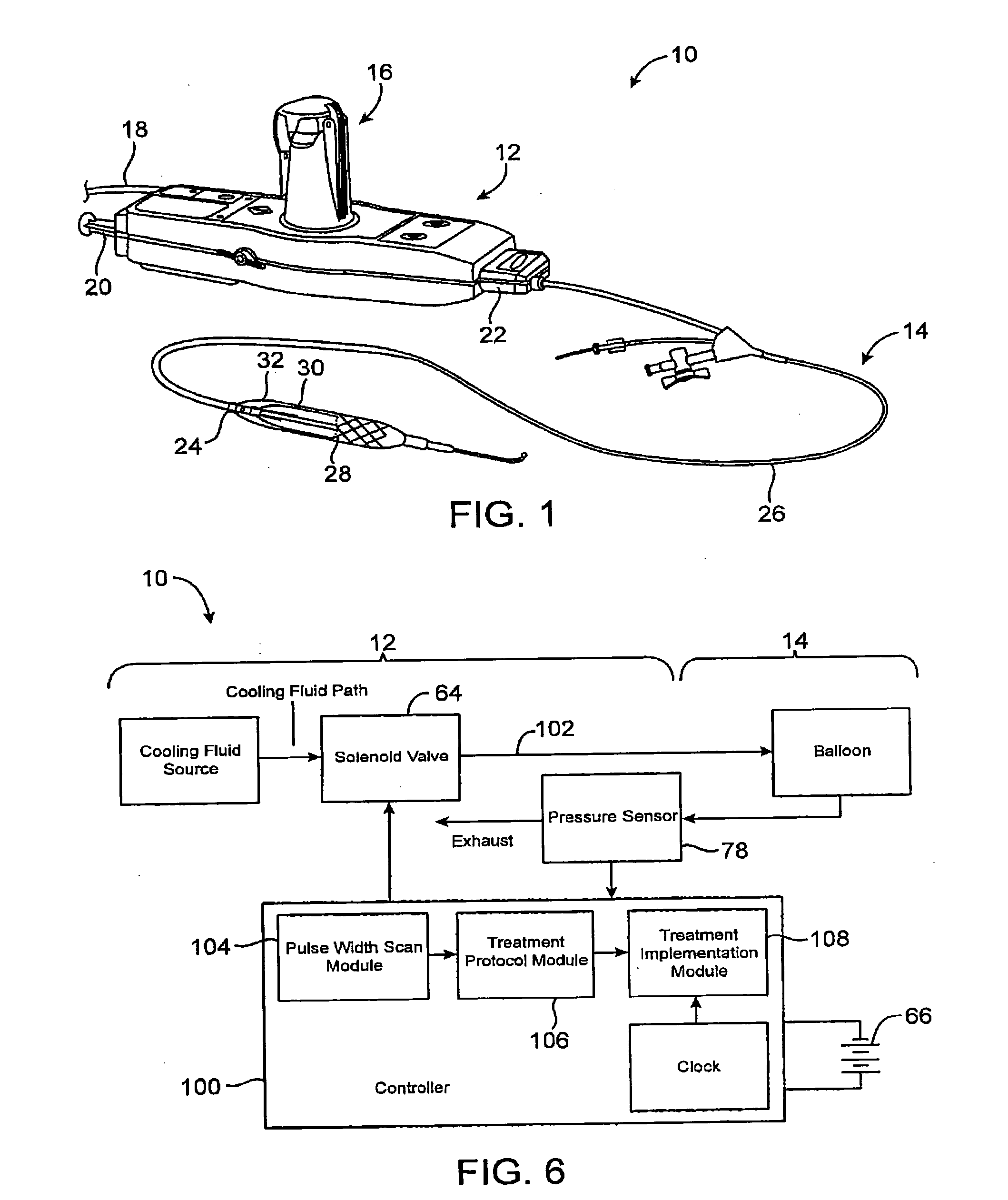
[0010] The treatment protocol will often be performed for the individual patient in a particular treatment setting, and the valve performance characteristic may be measured in that particular treatment setting. For example, when the patient is to be treated in a hospital room, the valve performance characteristic may also be measured in that hospital room, often just prior to treatment of the patient. This can facilitate duplicating the conditions of the treatment, for example, using the same system components, at the same ambient temperature and pressure, and the like.
[0013] The command pulse width can be measured using a controller of the probe system, with the controller of the probe system also implementing the treatment protocol by: a) transmitting a command pulse having the command pulse width to the valve; b) measuring a cooling fluid pressure adjacent to or downstream of the heat transfer surface along the fluid flow path in response to the preceding command pulse; c) comparing the measured pressure to a target pressure; d) repeating a)-c) in response to the measured pressure being less than the target pressure; and e) ending a)-d) in response to the measured pressure being greater than the target pressure. The target pressure can be changed as a function of time. For example, the target pressure may increase linearly as a function of increasing time, thereby providing a smooth and gradual increase in the inflation pressure. In some embodiments, the pressure may increase at a first rate during a first portion of the inflation cycle, and may then increase at a second rate during a second portion of the inflation cycle. For example, a relatively low initial inflation rate of less than 5 psi / sec. may be used to gradually open a balloon from a small profile configuration to a deployed profile configuration, and may then be followed by an inflation rate of over 5 psi / sec. to avoid excessive inflation times to dilation pressures. Such smooth and gradual inflation may avoid rapid movement or snapping of the balloon wall against adjacent tissues, and the like. Still further treatment pressure and / or temperature profiles are possible, with temperature and pressure of cryogenic fluids often being coupled by the relationship between vaporization temperature and pressure in a vaporization chamber in thermal contact with a treatment surface. Along with the ability to provide selected treatment temperatures and / or pressures, controlled rates of change of these parameters may be provided, differing dwell times at differing temperatures or pressures, repeated cycling of temperature / pressure excursions, and the like may also be employed.
[0019] The balloon will often be used to dilate the target tissue, and the balloon system may, or may not, effect cooling of the target tissue. Dilation pressure can be accurate controlled throughout the dilation treatment cycle, and visualization of the balloon may be facilitated by a radiopaque material disposed along the balloon. Surprisingly, such gas inflation may be easier and / or more repeatable than standard liquid and contrast inflation, thereby facilitating angioplasty, stenting, peripheral vessel dilation, and a variety of other balloon system treatments. The valve will often comprise a solenoid valve, and the valve performance characteristic is often measured by determining a minimum command pulse width for actuating the valve. At least a portion of the fluid comprises a liquid that vaporizes within the balloon.
[0022] A battery may be in electrical communication with the controller, and the controller may be configured to measure the valve performance characteristic and implement actuation of the valve so as to treat the tissue using the battery. The controller may be configured to measure the command pulse width by sequentially assessing candidate pulse widths while monitoring for cooling fluid with the sensor. The sequential candidate pulse widths may be assessed in an order from generally shorter pulse widths to generally longer pulse widths. While some variation in the order may be employed, maintaining the general trend of going from shorter pulse widths to longer pulse widths avoids unnecessary release of cooling fluid when a minimum effective pulse width is to be identified. The sensor may comprise a pressure sensor to indicate cooling fluid flow and / or pressure along the path, and the controller may be configured to determine the command pulse width by comparing the pressure along the cooling fluid path to a threshold pressure.

Problems solved by technology

While these procedures, particularly PTA and stenting, have gained wide acceptance, they continue to suffer from the subsequent occurrence of restenosis.
While these proposals have enjoyed varying levels of success, these procedures have not proven to be entirely successful in avoiding all occurrences of restenosis and hyperplasia in all locations, and the costs for implementing many can be excessive for many patients.

Method used


Image

  • Efficient controlled cryogenic fluid delivery into a balloon catheter and other treatment devices
  • Efficient controlled cryogenic fluid delivery into a balloon catheter and other treatment devices
  • Efficient controlled cryogenic fluid delivery into a balloon catheter and other treatment devices

Examples


Embodiment Construction

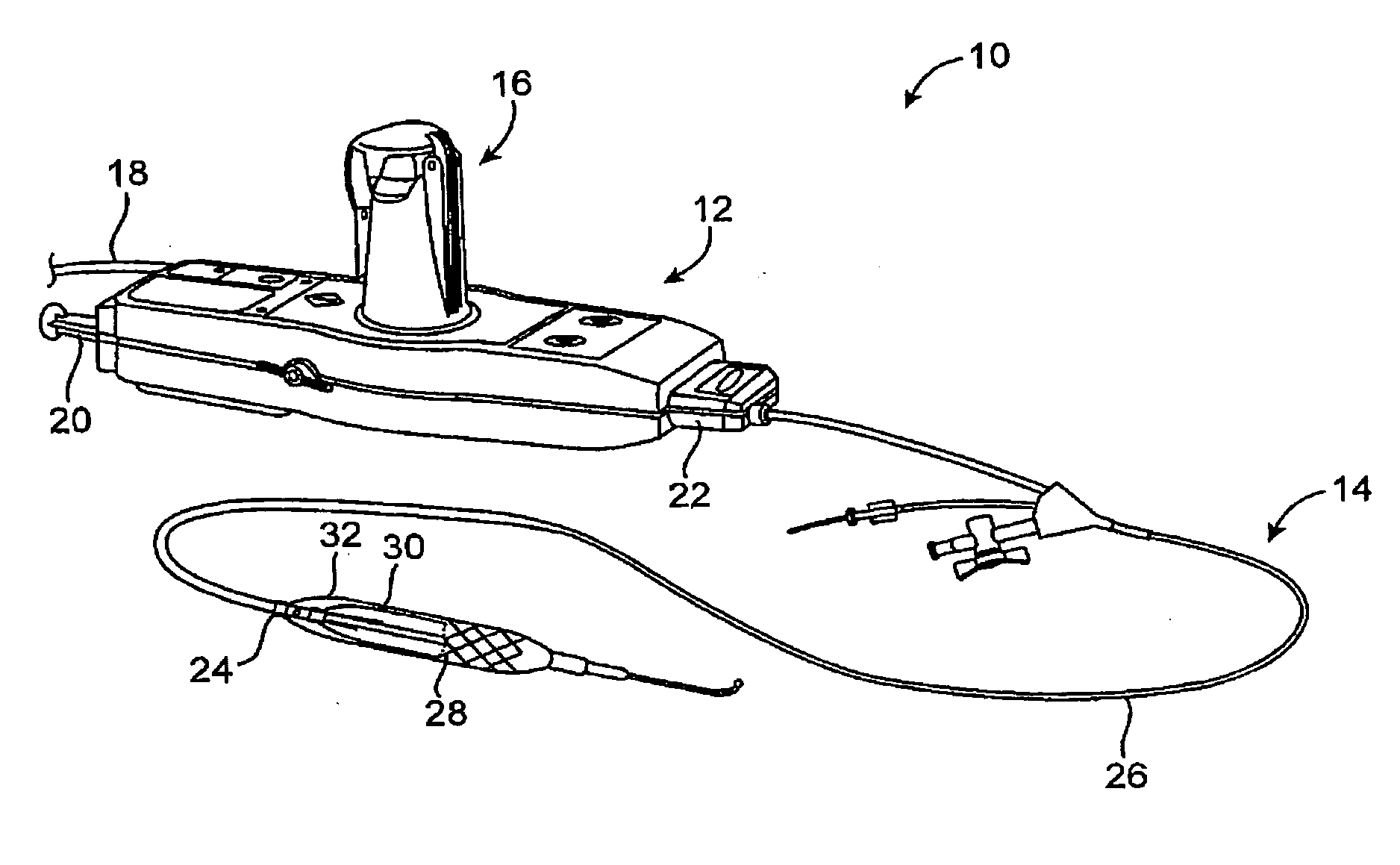
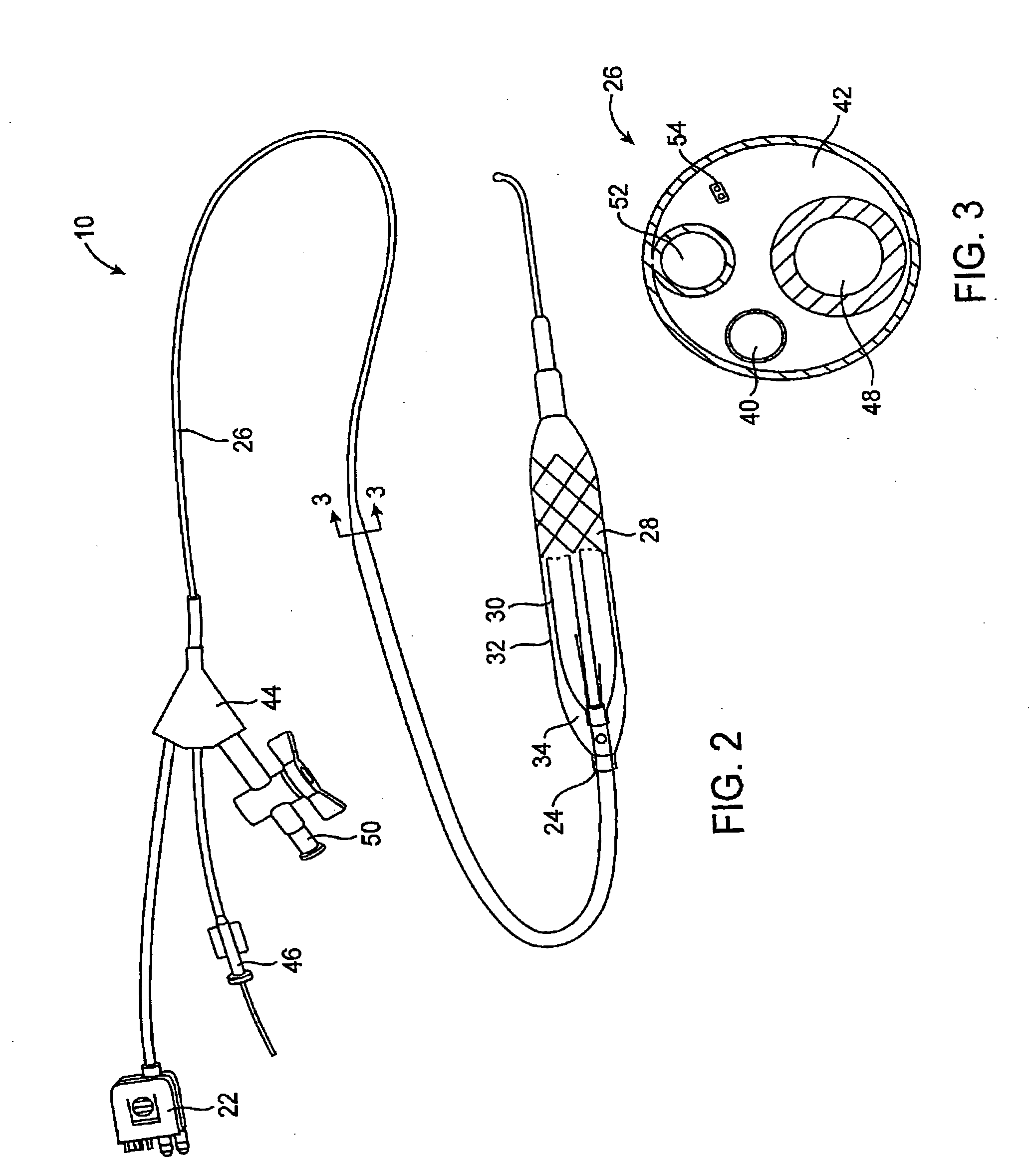
[0035] The present invention generally provides improved devices, systems, and methods for dilating and / or cooling treatments of the luminal wall in body lumens and other tissues of the body. The invention often makes use of a balloon which is inflated by a cooling fluid so as to radially engage a vessel wall (or other surrounding tissue). The cooling fluid will often change from a first phase to a second phase at least in part within the balloon, so that the latent heat of vaporization cools the surrounding tissues. Introduction of suitable cooling fluids is capable of very rapidly expanding the balloon once the cooling fluid begins to boil from a liquid to a gas phase (often occurring soon after the fluid enters the catheter). The invention is capable of providing advantageous control over the balloon inflation process, for example, allowing smooth and gradual changes to the pressure state within the balloon over time. As pressure and temperature are related in cryogenic cooling s...


PUM


Abstract

Devices, systems, and methods efficiently dilate and / or cool blood vessels and other body tissues. Controlled cooling with balloon catheters and other probes may be effected by a change in phase of a cryogenic fluid, often after measuring a minimum pulse width for actuating an individual solenoid valve along the cooling fluid path, with the measured pulse width allowing gradual inflation of a balloon without excessive venting of cooling fluid.

Description

BACKGROUND OF THE INVENTION [0001] The present invention relates generally to apparatus and methods for treatment of tissues using cooling and / or balloon inflation. In many embodiments; the invention provides systems, devices, and methods for cryogenically treating a patient's vasculature or other tissues by cooling the tissues to a temperature in a target temperature range, with cooling fluid pressure and / or the temperature control often being enhanced by measuring one or more characteristics of a cooling fluid flow control valve. Some embodiments may effect controlled inflation of tissue treating balloons with vaporizing and / or gaseous inflation fluids with or without therapeutic tissue cooling. [0002] A number of percutaneous intravascular procedures have been developed for treating atherosclerotic disease in a patient's vasculature. The most successful of these treatments is percutaneous transluminal angioplasty (PTA). PTA employs a catheter having an expansible distal end, usua...

Claims


Application Information

Patent Timeline
IPC IPC(8): A61B18/02A61F7/00A61F7/12
CPCA61B18/02A61B2018/0022A61F2007/126A61F7/123A61B2018/0212A61B2018/00744
Inventor REYNOLDS, BYRON
Owner BOSTON SCI SCIMED INC
Learn More