

Remodeling a cardiac annulus
a heart valve and annulus technology, applied in the field of medical devices and methods, can solve the problems that neither the terms used to describe a particular subset of surgical or other procedures should be interpreted as restricting, and achieve the effect of constricting the heart valve annulus and preserving the mobility of the valve leaflets
- Summary
- Abstract
- Description
- Claims
- Application Information
AI Technical Summary
Benefits of technology
Problems solved by technology
Method used
Image

Examples
example 1
[0115]FIGS. 20A to 20D illustrate a schematic example of a non-percutaneous insertion of a plurality of anchors that are inserted one at a time by deploying individual anchors from the end of a deployment device. The mitral valve annulus may be exposed by incising the left atrium. A first anchor may be aligned on the deployment device using a loading tool which orients the legs of the anchor (e.g., parallel to the shaft of the deployment device), so that the tips of the anchor's legs can be flush with the tip of the device. The tether can then be threaded through a slot in delivery device so that it passes through an eyelet of the anchor. The tip of the delivery device can then be positioned under a leaflet near the posterior commiusure 2001 as shown in FIG. 20A. The end of the deployment device (from which the anchor will be released) is pointed radially outward so that the tip contacts the ventricular wall, just below the annulus. In one variation, the anchor is deployed by squeez...
example 2
[0121] As described above, surgical annuloplasty typically constricts the diameter of the valve by suturing an ring (having a diameter that is smaller than the dysfunctional diameter of the annulus) directly to the annular tissue. Other methods of constricting the annuls involve placing devices in regions of the heart (e.g., the CS that are located in compliant fatty tissue outside of the atrium) that are remote from the annulus. Such methods may limit the effectiveness of the annuloplasty, the ability to constrict the annulus, and particularly the ability to constrict and retain the annulus for extended periods of time while not substantially limiting the range of motion of the valve leaflets
[0122]FIG. 22 graphically summarizes the results of the subvalvular approach described herein. Sheep were operated on as described, so that a cinchable assembly (e.g., anchors and a tether) was implanted and cinched to constrict the mitral valve orifice. As can be seen from the table in FIG. 2...
example 3
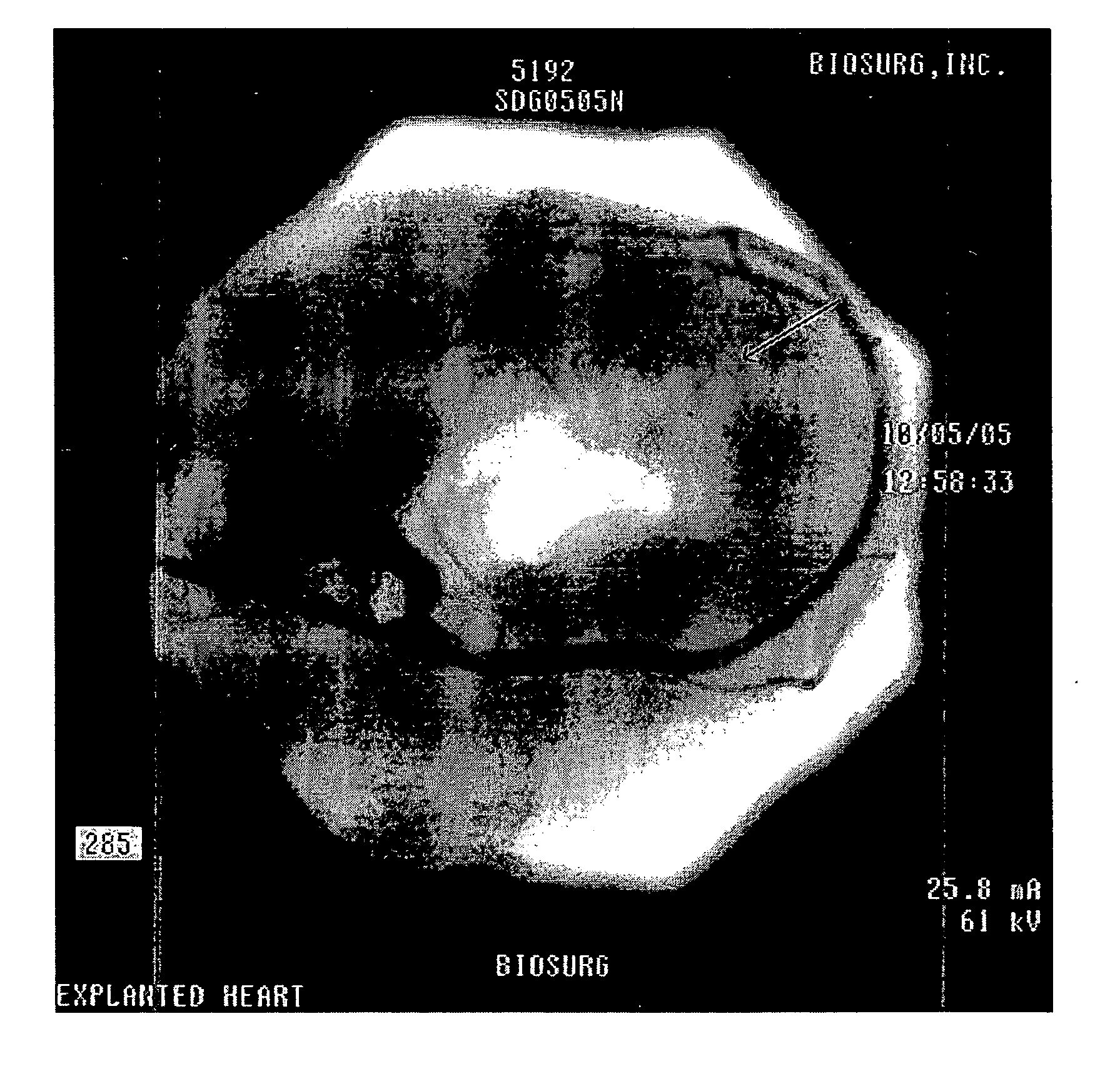
[0125] Animals in which the cinchable assemblies had been chronically implanted (e.g., 1-6 months) were examined to determine the response of the annular tissue to the implant. All of the excised hearts showed extensive fibrous tissue coverage of the implant, as well as ingrowth by fibrous tissue. For example, FIG. 25 shows a dissected mitral valve annulus containing a heart having a implant which was present for approximately three months. As can be seen, assembly has been encapsulated in scar tissue 2501 (fibrous tissue). This fibrous tissue is resilient (e.g., strong) and resists expansion, even after cutting the tether of the assembly.
[0126] This encapsulation may also be seen in cross-sections through the tissue, as seen in FIG. 26A-26B. FIG. 26 also illustrates the infiltration of fibrous tissue into the implants. Infiltration of fibrous tissue into the cinchable assembly can result the formation of a new annular band. FIG. 27 also illustrates cross-sections from a heart in w...
PUM
 Abstract
Description
Claims
Application Information