Reactor manufacturing method for a fuel cell processor

a fuel cell and reactor technology, applied in the direction of machines/engines, metal/metal-oxide/metal-hydroxide catalysts, chemical/physical processes, etc., can solve the problems of automobile honeycomb monolith exhaust catalytic reactors, often detrimental to the development of laminar flow of honeycomb monoliths, and mass transportation problems

Inactive Publication Date: 2006-06-22
GM GLOBAL TECH OPERATIONS LLC
View PDF22 Cites 6 Cited by
  • Summary
  • Abstract
  • Description
  • Claims
  • Application Information

AI Technical Summary

Benefits of technology

[0011] To overcome the drawbacks and disadvantages of the above design approaches, and to meet the necessary design conditions noted, disclosed herein is a method of forming a catalyst bed. The method provides a metal support comprising a metal foil perforated with a plurality of apertures or holes of different sizes and shapes integrated throughout the foil. The perforated foil is then heat treated, washcoated, catalyzed and cured. The bed is assembled by either layering individual segments of the perforated, washcoated and catalyzed foil or spirally rolling a predetermined length of prepared foil strip. By combining shaped sections, in either segments or a rolled coil, with a plurality of apertures, a uniform longitudinal and radial flow path is provided throughout the bed, thus providing for controlled temperature and reaction rate throughout the bed.

Problems solved by technology

Drawbacks exist, however, for honeycomb monolith catalyst systems in fuel cell fuel processor system applications.
Also, automobile honeycomb monolith exhaust catalytic reactors often detrimentally develop laminar flow through large sections of the straight, continuous, channels of their honeycomb structure.
This creates mass transport problems, and the only effective means for distributing heat is axially, along the length of the channels.
If any over-temperature condition develops in the inlet section, where turbulence does exist, or if any blockage or unequal distribution of inlet feed exists, there is no means by which the reactants can migrate from one channel to another in a single monolith, or redistribute the reactant flow some distance downstream from a blockage.
This approach also has drawbacks, however, in that washcoating and catalyst loading are performed after assembly, which can result in non-uniform washcoating and catalyst loading throughout the offset monolith.
After-assembly washcoat and catalyst loading is both extremely difficult and cost ineffective to both prepare and subsequently to retain the catalyst structure without physical damage to the washcoat or catalyst layer(s).
The disadvantage of this support structure is similar to the “sliced honeycomb monolith” in that washcoating and catalyzing the surfaces requires forcing a slurry of the washcoat and / or catalyst material through its webbed structure after assembly.
Washcoating these supports uniformly throughout the structure can be very problematic, particularly when cell density is relatively high.
In addition, these supports have been found to be very non-uniform in both cell size and cell distribution.
This results in areas where blockages occur because of fabrication faults, making coating and distribution activity less controlled.
A further disadvantage is that backpressure through these monoliths is higher than for the honeycomb monoliths.
Uniformly controllable washcoat and catalyst loading is not available with the honeycomb or foam support design catalytic beds.

Method used


Image

  • Reactor manufacturing method for a fuel cell processor
  • Reactor manufacturing method for a fuel cell processor
  • Reactor manufacturing method for a fuel cell processor

Examples


Embodiment Construction

[0033] The following description of the preferred embodiment(s) is merely exemplary in nature and is in no way intended to limit the invention, its application, or uses. Variations that do not depart from the jist of the invention are intended to be within the scope of the invention. Such variations are not to be regarded as a departure from the spirit and scope of the invention.

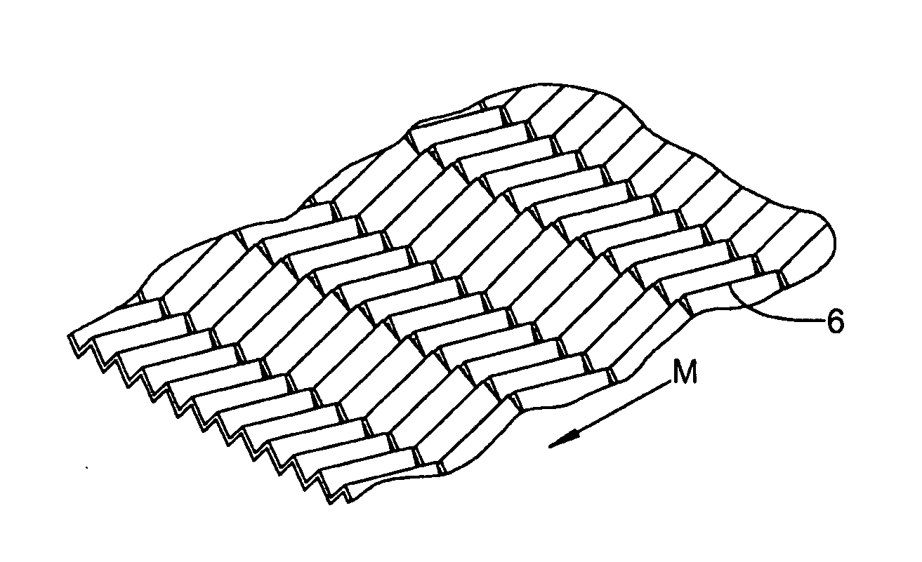
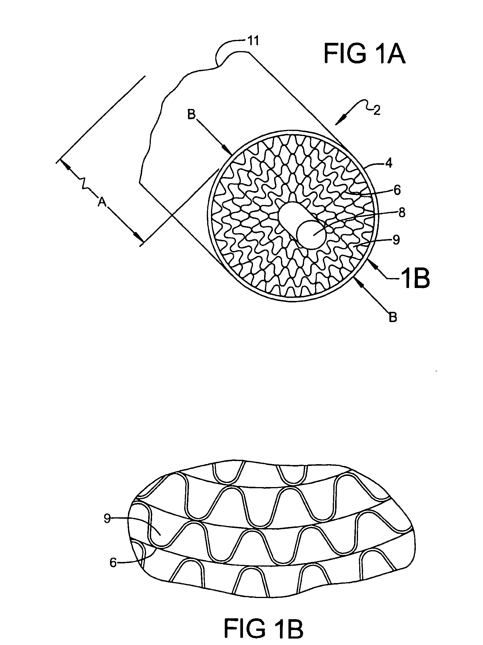
[0034] Referring to FIG. 1A, a catalytic reactor assembly 2 of the present invention is disclosed. Catalytic reactor assembly 2 includes an outer body 4, a catalytic bed having a series of metal foil layers 6, and a central mandrel 8. In this configuration, a catalytic bed length A and a catalytic bed diameter B are represented. Flow through the metal foil layer 6, will enter through an inlet end 9 of catalytic reactor assembly 2 and travel through the paths of the metal foil layers 6 to an exit end 11 of catalytic reactor assembly 2. Referring now to FIG. 1B an exploded view of inlet end 9 of the rolled co...


PUM

PropertyMeasurementUnit
thicknessaaaaaaaaaa
thicknessaaaaaaaaaa
thicknessaaaaaaaaaa

Abstract

A method to produce a catalytic bed is initiated by forming apertures in a predetermined pattern on a strip or segment of thin foil. A pattern of desired channels is formed into the apertured foil, for example, as a herringbone pattern. The patterned foil is heat treated, and the surfaces of the foil are provided with at least one washcoat and at least one catalyzed coat, and cured. Cured foil in strip form is rolled into a multi-layer coil, or cured foil in segment form is stacked in multiple segment layers, to produce a desired geometric shape of the catalytic bed. The channels between layers of foil are offset in each successive layer to preclude channel nesting. The offset channels and apertures provide turbulent longitudinal and radial flow of a desired material throughout the catalytic bed.

Description

FIELD OF THE INVENTION [0001] The present invention relates to a catalytic reactor for a fuel cell system, and more specifically to a method for manufacturing a catalytic reactor having a perforated metal support providing uniform wash coat catalyst loading and distribution, and turbulent flow throughout the reactor. BACKGROUND OF THE INVENTION [0002] Operating conditions of a catalyst system in an exemplary industrial process catalytic reactor cover a relatively small range of variables. The flow ranges in an exemplary industrial process are no more than 4 or 5:1, the inlet flow and mixing conditions are well defined, and the reaction zones are also closely controlled to produce temperature profiles that are maintained within a narrow range. Start conditions are carefully controlled to assure the catalyst and reactor are performing according to prescribed conditions. This type of operation leads to catalyst system designs that have less demanding requirements compared to operations...

Claims


Application Information

Patent Timeline
Patent Type & Authority Applications(United States)
IPC IPC(8): B21D51/16B21B1/46
CPCB21D13/10F01N3/2814Y10T29/49345Y10T29/49982Y10T29/4998
Inventor PETTIT, WILLIAM H.VOECKS, GERALD E.
Owner GM GLOBAL TECH OPERATIONS LLC
Why Eureka
Try Eureka