Restricted radiated heating assembly for high temperature processing

a heating assembly and high temperature processing technology, applied in the direction of chemically reactive gases, crystal growth process, coatings, etc., can solve the problems of resistive heating, filament expansion, filament distortion, etc., and achieve the effect of reducing the difference in resistan

Active Publication Date: 2006-06-22
CREE INC
View PDF21 Cites 43 Cited by
  • Summary
  • Abstract
  • Description
  • Claims
  • Application Information

AI Technical Summary

Benefits of technology

[0018] In one aspect, the invention is a conductive filament for resistive heating in vapor deposition that comprises a cathode contact and an anode contact, a plurality of concentrically adjacent arc-shaped portions between the contacts that define corresponding arc-shaped openings therebetween, a plurality of respective turns connecting pairs of the arc-shaped portions, with at least one of the turns having a width across the filament at the turn that is less than the width across the adjacent arc-shaped portions for reducing the difference in resistance between the inner and outer edges of the turn as current flows through the filament between the contacts.
[0021] In yet another aspect, the invention is a method of increasing the lifetime and productivity of a filament-based resistive-heated vapor deposition system. In this aspect the invention includes the steps of heating the filament while permitting the filament to move as it expands under the effect of increasing temperature and while limiting the expanding movement of the filament to an amount that prevents the expanding movement of the filament from creating undesired contact with any portion of the reactor, including the filament itself.
[0022] In another aspect, the invention is a conductive filament having a cathode contact and an anode contact and a rotational symmetry of order n, where n is at least 2, for minimizing the number of shapes the filament presents to current flowing therethrough during resistive heating.
[0023] In another aspect, the invention is a vapor deposition reactor that includes a reaction chamber, at least one conductive filament in the chamber, a pair of electrodes in the chamber and in electrical contact with the conductive filament, and insulating protective covers on portions of the electrodes for preventing deposition reactants, products and byproducts from undesirably contacting the electrodes.

Problems solved by technology

Nevertheless, resistive heating also presents some inherent disadvantages.
First, the filaments tend to expand at the high temperatures typically required for CVD.
Such expansion frequently leads the filament to become distorted because of the difference in thermal properties (including coefficient of thermal expansion) between the filament and the various other components in the reactor.
Such deformation can change the characteristics of the reactor's behavior from run to run and can reduce the lifetime of the heating assembly.
Second, resistive heating often creates large thermal gradients across portions of the reactor assembly.
These large gradients can lead to cracking in the components.
Third, the electrodes that carry current to the filament are typically exposed to the growth environment and thus to the reactants, products, and by-products at high temperatures.
As a result, undesired materials can accumulate on the electrodes and the electrodes can become electrically shorted to one another or to other components of the reactor.
Fourth, in some types of systems, the filaments are permitted to move inside of the growth apparatus as they expand and can form undesired electrical shunts (short circuits) with other components in the reactor.
Additionally, such expansion can cause undesired contact between different portions of the same filament.
Although not necessarily causing a short circuit, such filament self-contact can change the current flow (and thus the temperature) though the filament and lead to loss of temperature control or early degradation.
These problems can become exacerbated when, as is typical in many reactors, more than one filament is used.
As another factor, the number of components required in a resistive heating assembly is relatively high providing a corresponding set of opportunities for component failure and overall difficulty.
Ordinary cleaning takes at least about two hours and more complex maintenance, considerably longer.
The cumulative problems in resistive heating that have been noted herein tend to increase the frequency with which such maintenance or repair must take place.

Method used


Image

  • Restricted radiated heating assembly for high temperature processing
  • Restricted radiated heating assembly for high temperature processing
  • Restricted radiated heating assembly for high temperature processing

Examples


Embodiment Construction

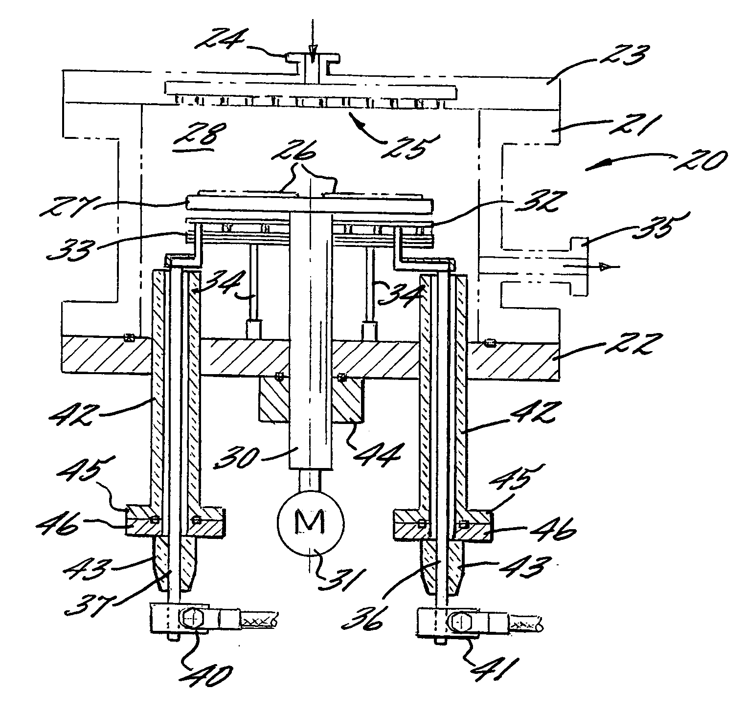
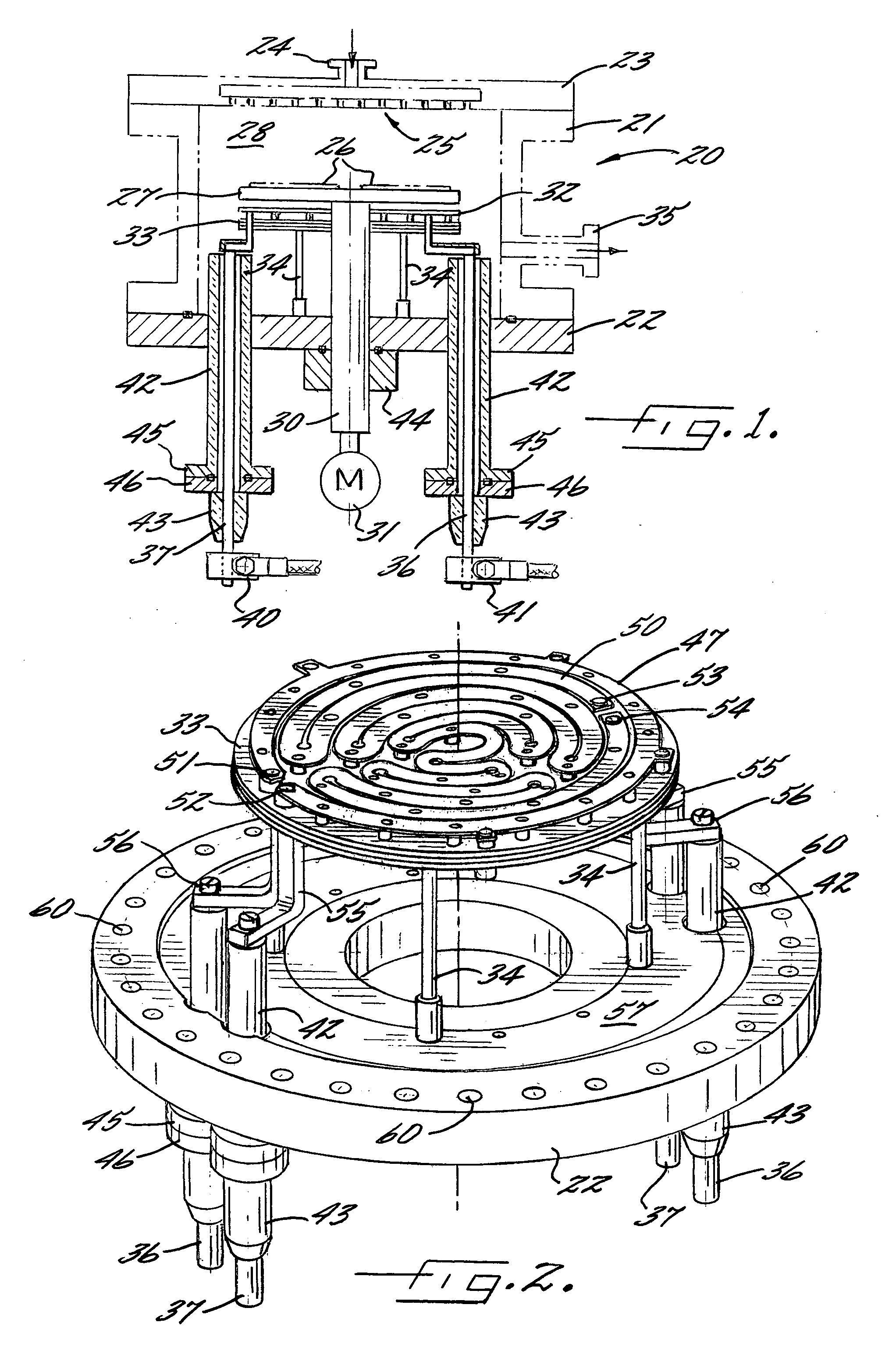
[0037]FIG. 1 is a cross-sectional view of a vapor deposition reactor broadly designated at 20. Although the invention will be described with respect to the figures, those of skill in this art will recognize that a number of variations on the exact type and style of the reactor can be used while still incorporating the claimed invention. Accordingly, FIG. 1 and the other figures herein, are exemplary rather than limiting of the invention.

[0038] The reactor 20 is generally cylindrical in shape and includes annular walls 21, a circular floor or base plate 22, and a circular top portion 23 that together define a chamber 28. In the style of reactor illustrated in FIG. 1, the top portion 23 also includes a gas inlet 24 and a manifold broadly designated at 25 (sometimes referred to as a “shower head”) for more evenly distributing incoming gases into the chamber 28 and across the substrates 26 upon which deposition growth is to take place.

[0039] The substrates 20 typically rest on a subst...


PUM

PropertyMeasurementUnit
temperatureaaaaaaaaaa
conductiveaaaaaaaaaa
resistanceaaaaaaaaaa

Abstract

A vapor deposition reactor and associated method are disclosed that increase the lifetime and productivity of a filament-based resistive-heated vapor deposition system. The reactor and method provide for heating the filament while permitting the filament to move as it expands under the effect of increasing temperature while limiting the expanding movement of the filament to an amount that prevents the expanding movement of the filament from creating undesired contact with any portions of the reactor.

Description

[0001] This application claims priority from application Ser. No. 60 / 627,815 filed Nov. 15, 2004.BACKGROUND [0002] The present invention relates to vapor deposition techniques for material growth and in particular relates to chemical vapor deposition growth of epitaxial layers of semiconductor materials. [0003] The term “vapor deposition” is used to refer to a number of techniques in which gas phase precursors condense or react to form a layer of a desired material on a substrate. Similarly, the phrase “chemical vapor deposition” (“CVD”) is often used to refer to a growth technique in which gas compositions react on a substrate surface to produce a desired product in the form of a high purity; high crystal quality epitaxial layer. Such layers are required for a number of semiconductor devices including, but not limited to, light emitting diodes (“LEDs”). [0004] The physical and chemical characteristics of many semiconductor materials requires that their growth using CVD or related t...

Claims


Application Information

Patent Timeline
Patent Type & Authority Applications(United States)
IPC IPC(8): C23C16/00
CPCC23C16/46H01L21/67103C30B25/105
Inventor EMERSON, DAVID TODDGARNER, ROBERT ALLENBERGMANN, MICHAEL JOHNBROWN, KEENAN CARLYLEPENNINGTON, MICHAEL ALLENCOLEMAN, THOMAS GOLDTHWAITE
Owner CREE INC
Why Eureka
Try Eureka