Pneumatic tire for two-wheeled motor vehicle

Inactive Publication Date: 2006-06-22
BRIDGESTONE CORP
View PDF7 Cites 29 Cited by
  • Summary
  • Abstract
  • Description
  • Claims
  • Application Information

AI Technical Summary

Benefits of technology

[0038] In contrast, in the present second invention, by combining the tilting main groove A and the tilting main groove B, and particularly, by optimally disposing these grooves in integral and balanced manners, it is feasible to improve cornering grip due to the pattern edge effect with respect to the input in the tilting main grooves that forms truncated chevron forms as viewed from the rear side of a rotational direction of the tire, and inhibit the reduction in the pattern rigidity during cornering in the tilting main grooves that forms inverted truncated chevron forms as viewed from the rear side of a rotational direction of the tire. This allows the enhancement of the cornering grip performance under “dry” conditions, thereby reducing the deterioration of uneven wear resistance to a minimum.
[0039] Also, installing the tilting main groove A and the tilting main groove B in combination enables the distribution of the bending rigidity of the tread portion in the ground-contacting portion during cornering to be optimized. Thereby, the ground-contacting property is improved and the cornering grip and turning capability is enhanced, and hence, the above-described advantages can be exploited to the maximum extent possible for important performance suited to various usage, and the disadv

Problems solved by technology

However, the spiral configuration originally has the drawback of having a low tread surface bending rigidity (in the tread width direction), and therefore, it has involved problems with steering performance, such as a poor handling response and a low grip force with respect to a road surface.
Also, in the spiral belt configuration constituted only by steel cords, merely lowering the driving count of cords would have detrimental effects, such as a reduction in anti-fatigue properties of tread rubber and a ply material with respect to repetitive bending, due to a reduction in the breaking strength with respect to pneumatic pressure, a decrease in the puncture resistance, a reduction in bending rigidity in the close-sectional direction.
However, in the conventional radial tire for a two-wheeled motor vehicle, which has used in combination of a spiral belt and an angled belt, the distribution of bending rigidity in the tread region has not been optimized, so that the overall settling of vibrations of a vehicle body, slip-control performance, capability of absorbing unevenness of a road surface have not sufficiently been optimized.
However, such countermeasures have not been able to attain the optimization of tensile rigi

Method used


Image

  • Pneumatic tire for two-wheeled motor vehicle
  • Pneumatic tire for two-wheeled motor vehicle
  • Pneumatic tire for two-wheeled motor vehicle

Examples


example 1

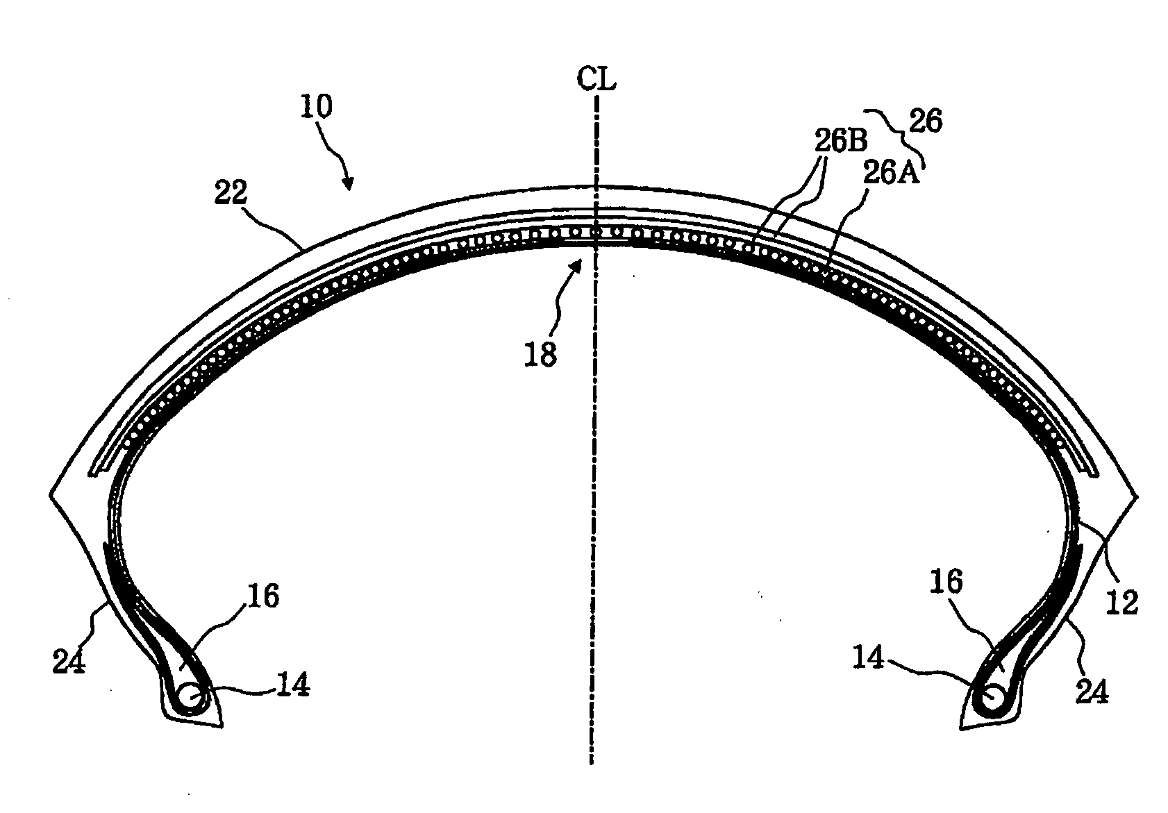
[0090] The pneumatic tire 10 for a two-wheeled motor vehicle according to the embodiment shown in FIG. 1 was used as a rear tire. This tire has a size of 190 / 50ZR17, and is provided with two nylon carcass plies and bead fillers having a hardness of 95° (Shore A hardness).

[0091] The spiral belt 26A was formed by spirally winding one long length of rubber-coated cord made of aramid fibers (Kevlar™ made by du Pont Corp.; twisted structure: 1670d / 2; initial tensile resistance: 736 cN / cord) obtained by coating the cord with rubber. The driving count was 30 cords / 25 mm.

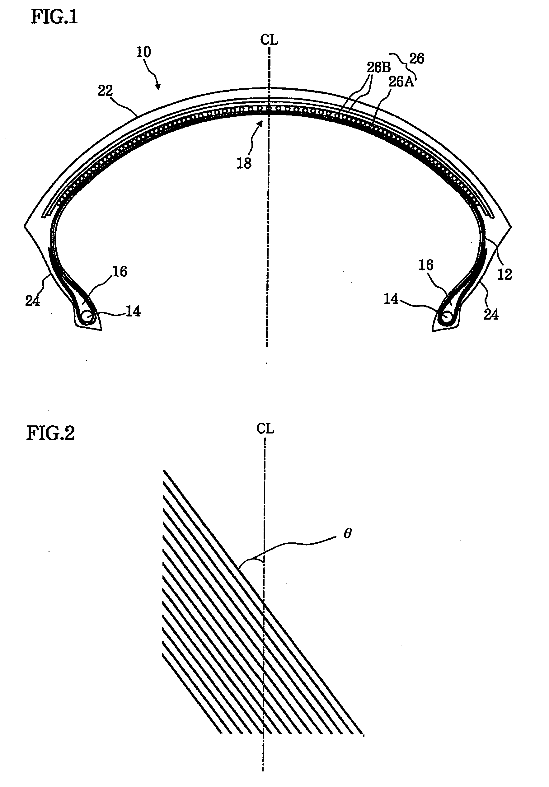
[0092] On the other hand, the two angled belt 26B provided on the out layer of the spiral belt 26A are belt plies (driving count: 18 cords / 25 mm) of cords made of aramid fibers (Kevlar™ made by du Pont Corp.; twisted structure: 1670d / 2; initial tensile resistance: 736 cN / cord). The cord angle thereof is 45° with respect to the equatorial plane of the tire. The two angled belts 26B cross each other, and simultaneously, til...

example 2

CONVENTIONAL EXAMPLE 2

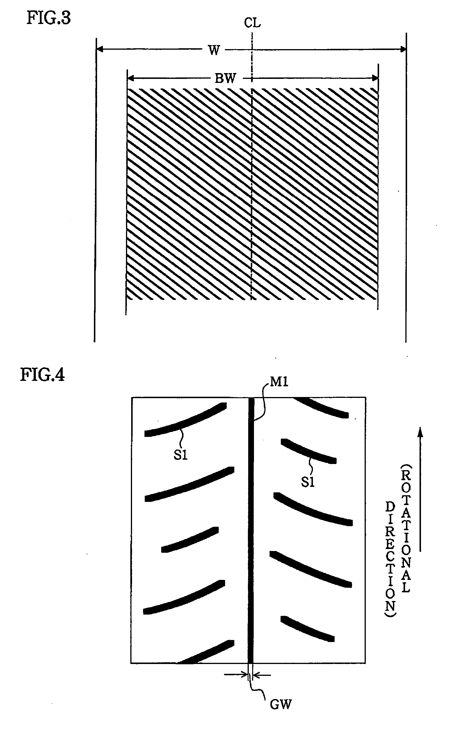
[0096] The same rear tire as that used in the example was employed as a sample tire, with the exception that the type shown in FIG. 13 was used for a pattern on the tread surface portion in the tread 22. In the tread pattern shown in FIG. 13, the main groove component M1 in FIG. 4 does not exist, and tilting main grooves S4, which form truncated chevron shapes as viewed from the rear side of the rotational direction of the tire, extend beyond the tread center portion alternately on the right and left sides, and opposing ends of the tilting main grooves S4 mutually couple in an alternating manner, thereby forming chevron shapes. The area ratio of all grooves in a pattern on the tread surface portion is substantially the same as that in the example 1.

[0097] With each of these tires mounted to a vehicle as a respective one of the rear tires, a conventional tire having a size of 120 / 70ZR17 was mounted as a front tire in each case, and running tests were performed....

example 3

CONVENTIONAL EXAMPLE 3

[0116] The same front tire as that used in the example 3 was used as a sample tire, with the exception that the type shown in FIG. 14 was used for a pattern on the tread surface portion in the tread 22. In the tread pattern shown in FIG. 14, a main groove component C4 exists, and there are provided tilting main grooves S5, which form truncated chevron shapes as viewed from the rear side of the rotational direction of the tire. The area ratio of all grooves in a pattern on the tread surface portion is substantially the same as that in the example 3.

CONVENTIONAL EXAMPLE 4

[0117] The same front tire as that used in the example 3 was used as a sample tire, with the exception that the type shown in FIG. 15 was used for a pattern on the tread surface portion in the tread 22. In the tread pattern shown in FIG. 15, a main groove component C5 exists, and there are provided tilting main grooves S6, which form inverted truncated chevron shapes as viewed from the rear sid...


PUM


Abstract

A pneumatic tire for a two-wheeled motor vehicle in which a belt layer 26 includes a spiral belt (26A) where the direction of its cords is substantially a circumferential direction of the tire, and at least one angled belt (26B) that is provided on at least an outer layer of the spiral belt (26A) and whose cords have an angle with respect to an equatorial plane of the tire. On a tread surface portion of a tread (22) of the tire, there is provided, at least in a tread center region, a main groove component having an angle in the range of 0° or more to less than 20° with respect to the circumferential direction. Thus, a pneumatic tire for a two-wheeled motor vehicle is provided that is applicable to a front or rear wheel, and that possesses improved kinematical performance including the turning capability at a corner, grip limit, overall settling of vibrations of a vehicle body, slip-control performance, capability of absorbing unevenness of a road surface, and enhanced steering stability, which are realized by making use of respective advantageous characteristics of the respective belts.

Description

TECHNICAL FIELD [0001] The present invention relates to a pneumatic tire for a two-wheeled motor vehicle. More specifically, the present invention pertains to a pneumatic tire for a two-wheeled motor vehicle, capable of enhancing the steering stability by being applied to at least one of the front and the rear wheels, and a pneumatic tire for a two-wheeled motor vehicle, capable of balancedly improving various performance such as uneven-wear resistance, steering stability, capability of absorbing evenness of a road surface, etc. BACKGROUND ART [0002] With the recent advancement of weight reduction and performance enhancement in vehicles, the securing of their stability in ultrahigh-speed running has become ever more important. As a result, the conventional angled belt configuration in which the cord direction has a predetermined angle with respect to the equatorial plane of a tire, has been given way to the spiral belt configuration that is low in its variation in ground-contacting ...

Claims


Application Information

Patent Timeline
IPC IPC(8): B60C11/03B60C9/20B60C9/22B60C19/00
CPCB60C9/2009B60C9/22B60C9/2204Y10T152/10783B60C19/001B60C2200/10B60C11/0302
Inventor NAKAMURA, TSUTOMU
Owner BRIDGESTONE CORP
Why Eureka
Try Eureka