Multicarrier signal transmission apparatus, multicarrier signal receiving apparatus, multicarrier signal transmission method, multicarrier signal receiving method, and communication system

a multi-carrier signal and transmission apparatus technology, applied in the direction of electrical equipment, digital transmission, secret communication, etc., can solve the problems of large circuit size, large loss of information due to suppression, deterioration of reception quality, etc., and achieve the effect of simple configuration

Inactive Publication Date: 2006-06-22
FUJITSU LTD
View PDF8 Cites 22 Cited by
  • Summary
  • Abstract
  • Description
  • Claims
  • Application Information

AI Technical Summary

Benefits of technology

[0021] An object of the present invention is to provide a multicarrier signal transmission / receiving apparatus and transmission / receiving method able to be realized by a simple configuration and able to adjust the balance between the quality of reception and the generation of an out-band spurious wave.

Problems solved by technology

In the first peak suppression method, there is the advantage that it is possible to suppress the generation of a spurious wave outside the signal band since the peak suppression is performed before the band-limiting filter, however, there is the problem that since the peak suppression is performed on the modulated signals before multicarrier combination, the loss in the amount of information due to the suppression becomes large and a deterioration of the quality of reception is caused.
In the second peak suppression method, it is possible to suppress the signal loss due to peak suppression to a minimum, but there is the problem that a high frequency component occurs in the multicarrier signal and a spurious wave outside of the band ends up being generated.
Further, in the third peak suppression method, however, there is the problem that the size of the circuit becomes larger due to the provision of the filter.

Method used


Image

  • Multicarrier signal transmission apparatus, multicarrier signal receiving apparatus, multicarrier signal transmission method, multicarrier signal receiving method, and communication system
  • Multicarrier signal transmission apparatus, multicarrier signal receiving apparatus, multicarrier signal transmission method, multicarrier signal receiving method, and communication system
  • Multicarrier signal transmission apparatus, multicarrier signal receiving apparatus, multicarrier signal transmission method, multicarrier signal receiving method, and communication system

Examples


second embodiment

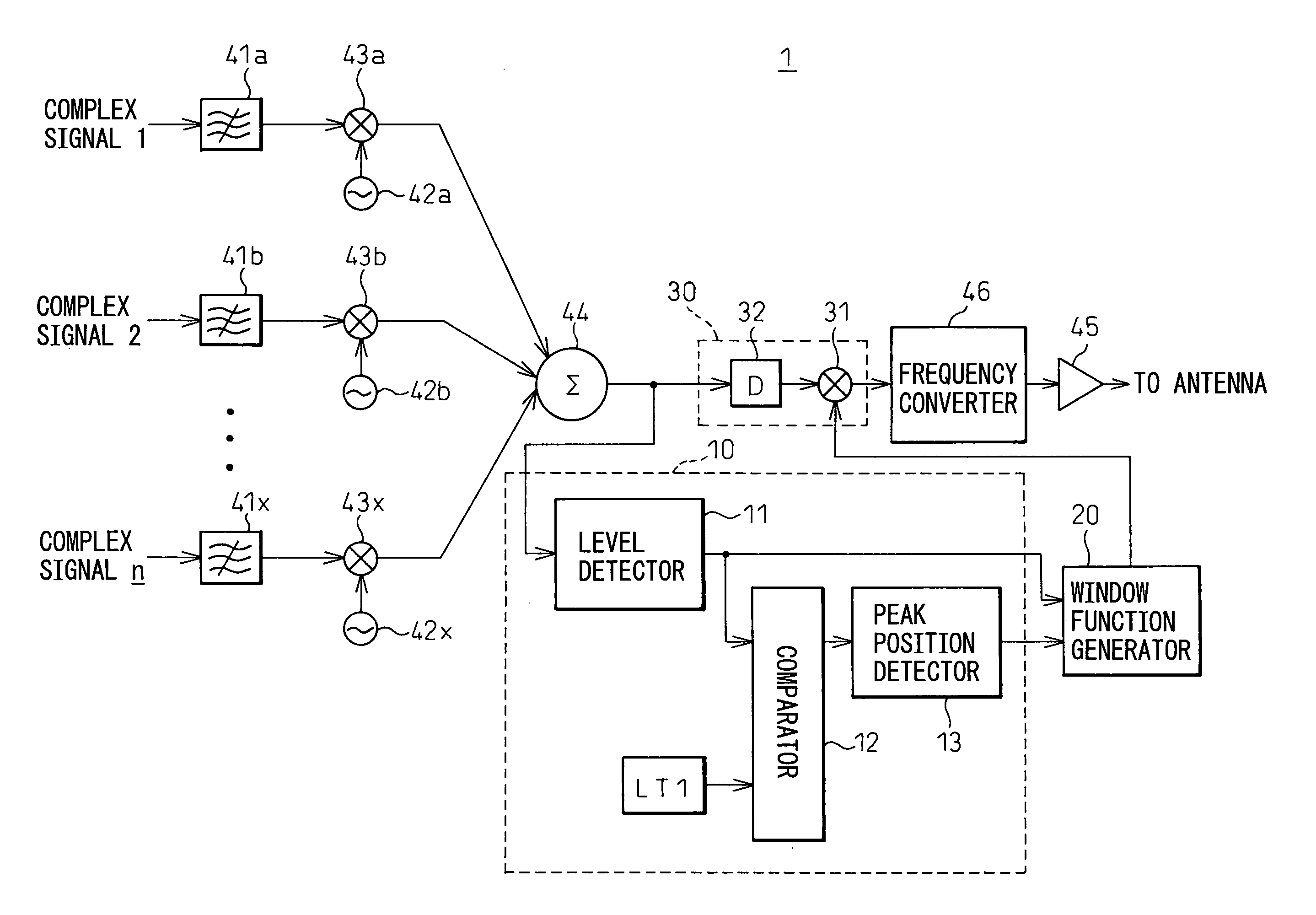
[0069]FIG. 5 is a schematic view of the configuration of a multicarrier signal transmission apparatus according to the present invention. As illustrated, the transmission apparatus 1 over-samples, then limits the bands of the plurality of digital baseband signals comprised by the complex signal 1, complex signal 2 . . . complex signal n by band-limiting filters 41a, 41b. . . 41x, respectively.

[0070] After this, sine wave generators 42a, 42b. . . 42x generate different frequency fa, fb . . . fx complex sine waves ejωt(ω=2πfa, 2πfb . . . 2πfx), while complex multipliers 43a, 43b. . . 43x multiply the same with the complex signal 1, complex signal 2 . . . complex signal n respectively to shift (up convert) them to the arbitrary frequencies.

[0071] Further, the complex signal 1 to complex signal n shifted to the frequencies and band limited are combined by a multicarrier combiner 44 into a multicarrier signal.

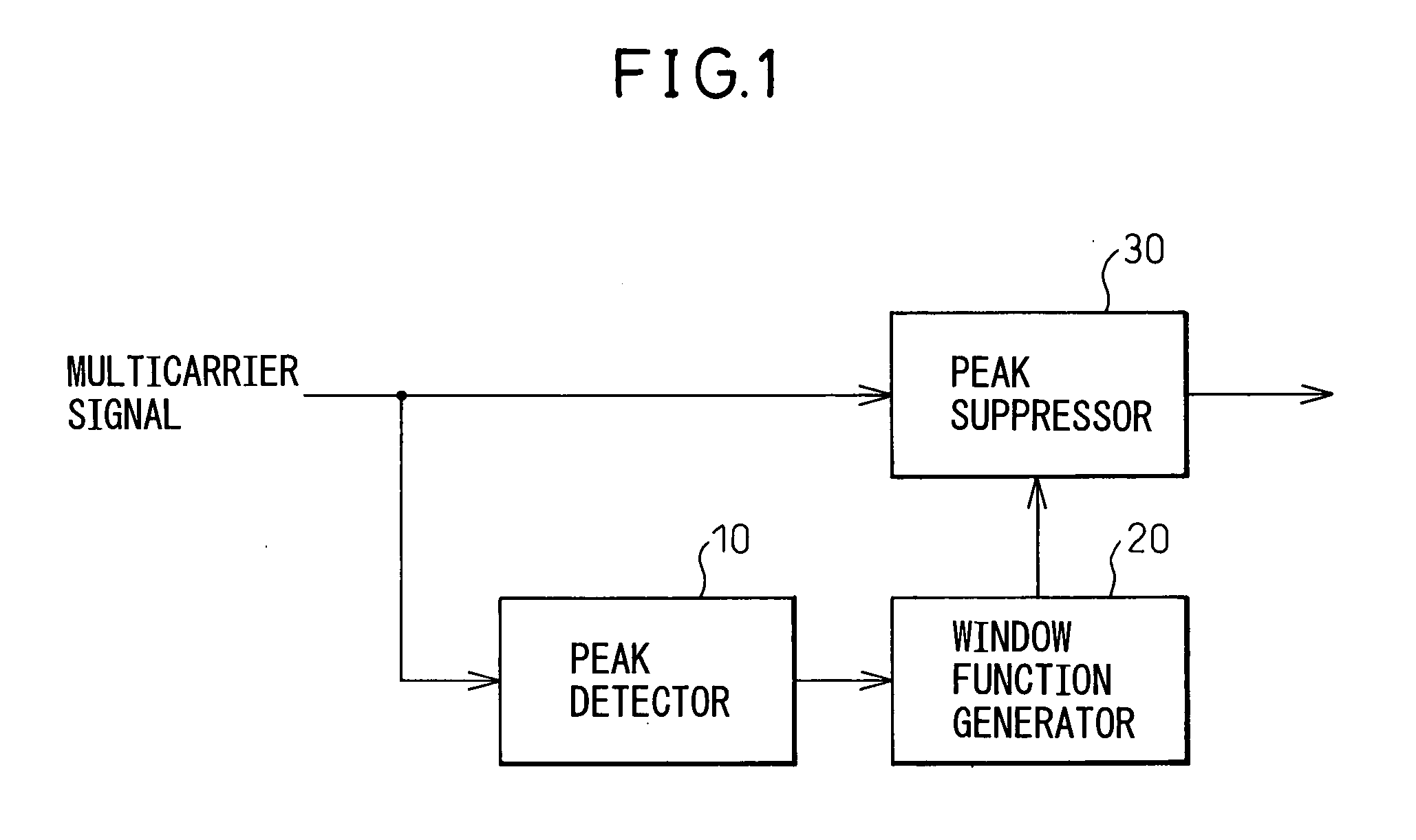
[0072] The peak detector 10 detects the peak levels of peak parts appearing i...

third embodiment

[0086]FIG. 8 is a schematic view of the configuration of a multicarrier signal transmission apparatus according to the present invention. The configuration shown in FIG. 8 shows the configuration of the peak detector 10 in the transmission apparatus 1 shown in FIG. 5 in more detail.

[0087] The peak detector 10 is provided with a level detector 11 for detecting the level of a multicarrier signal, a comparator 12 for comparing a detected level and predetermined level threshold LT1, and peak position detector 13 for detecting the peak positions of the signals of the peak parts of the multicarrier signal when the level of the detected multicarrier signal is over the level threshold LT1.

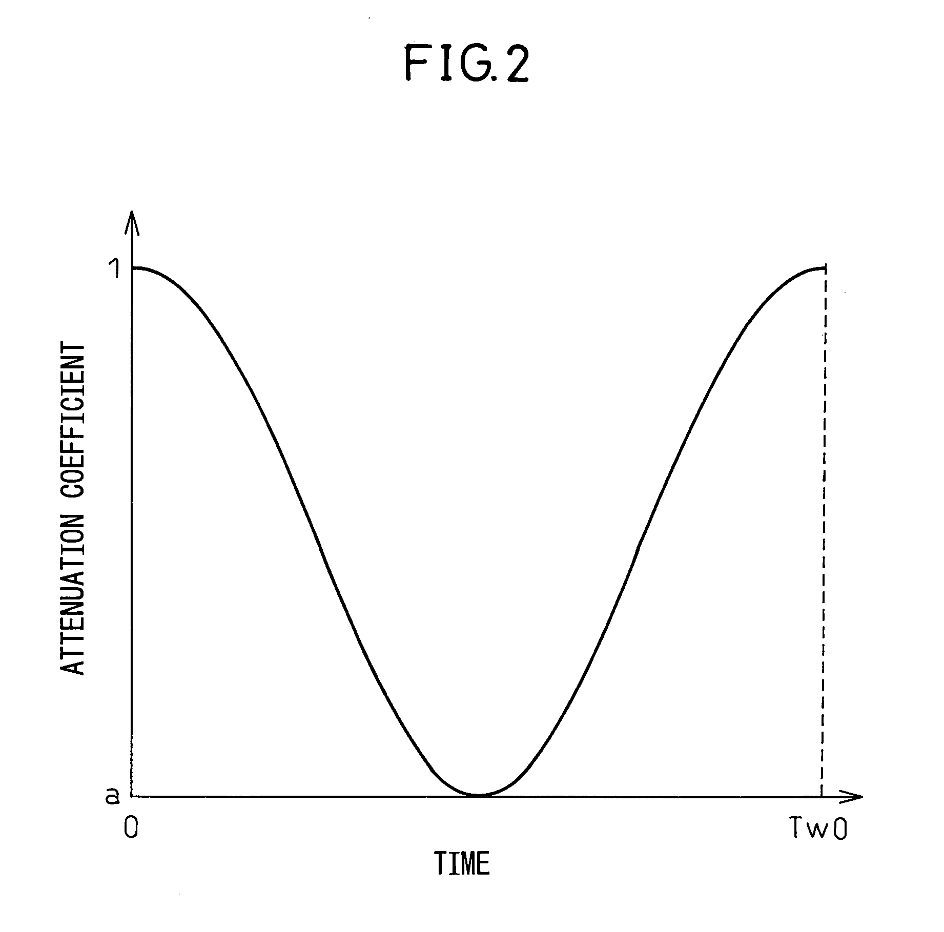
[0088] Further, at the point of time when the peak positions are detected, the window function generator 20 determines the amplitudes in accordance with the detection levels, generates window functions matching the timings centered on the peak positions, and multiplies them with the multicarrier signal by...

fourth embodiment

[0091]FIG. 10 is a schematic view of the configuration of a multicarrier signal transmission apparatus according to the present invention. The transmission apparatus 1 shown in FIG. 10 is provided with a period width detector 14 at the peak detector 10. The period width detector 14 detects the period widths of the peak parts of the multicarrier signal when the level of the detected multicarrier signal is over the level threshold LT1. The period widths of the peak parts may be set as period widths whereby the level of the multicarrier signal becomes over the level threshold LT1, may be set as period widths whereby it becomes at least another suitable level threshold, or may be set by detecting the half amplitudes of the peak parts.

[0092] The window function generator 20 determines the amplitudes in accordance with the detected level and generates window functions matched with timings centered on the peak positions. At this time, the period widths of the window functions generated are...


PUM


Abstract

A multicarrier signal transmission apparatus able to adjust the balance between the quality of reception and generation of an out-band spurious wave by a simple configuration, comprising a peak detector for detecting a peak part of a transmitted multicarrier signal, a window function generator for generating a window function of an amplitude in accordance with a peak level of a detected peak part, and a peak suppressor for attenuating the peak part in accordance with the value of the generated window function, and a multicarrier signal receiving apparatus, multicarrier signal transmission method, multicarrier signal receiving method, and communication system used with the same.

Description

CROSS REFERENCE TO RELATED APPLICATION [0001] This application is based upon and claims the benefit of priority from the prior Japanese Patent Application No. 2004-367761, filed on Dec. 20, 2004, the entire contents of which are incorporated herein by reference. BACKGROUND OF THE INVENTION [0002] 1. Field of the Invention [0003] The present invention relates to a transmission / receiving apparatus, transmission / receiving method, and communication system for a multicarrier signal combining a plurality of modulated signals, more particularly relates to a transmission / receiving apparatus, transmission / receiving method, and communication system for suppressing the peak power of a multicarrier signal to improve a peak-to-average power ratio (PAPR). [0004] 2. Description of the Related Art [0005] Digital wireless communication systems use multicarrier modulation schemes for combining a plurality of band-limited carrier signals and transmitting them by a high frequency carrier. FIG. 23 is a ...

Claims


Application Information

Patent Timeline
Patent Type & Authority Applications(United States)
IPC IPC(8): H04K1/10
CPCH04L27/2614
Inventor HAMADA, HAJIMEKUBO, TOKURONAGATANI, KAZUOISHIKAWA, HIROYOSHIFUDABA, NOBUKAZU
Owner FUJITSU LTD
Why Eureka
Try Eureka