
Image processing method, system, and apparatus for facilitating data transmission

a data transmission and image processing technology, applied in the field of image processing methods, can solve the problems of inability to meet the requirements of image transmission, inability to meet the requirements of image data transmission, so as to facilitate data transmission, facilitate image data transmission, and reduce the amount of image data transmission

Inactive Publication Date: 2006-06-22
INTELLECTUAL VENTURES I LLC
View PDF5 Cites 7 Cited by
  • Summary
  • Abstract
  • Description
  • Claims
  • Application Information

AI Technical Summary

Benefits of technology

"The present invention provides an image processing method for facilitating data transmission. The method uses a simple compression method to convert X-bits binary digital signals to a binary compressed data in a floating-point form of (1.n)*2m. This results in a reduction in the transmission amount of image data and facilitates the transmission rate of the image data. The method also includes a bit-enhanced technology to compensate decompressed image data to increase the accuracy of the recovery of the image data. Additionally, the method uses a simple image compression method to obtain the purpose of making the recovered image with low grayscale level non-distorted and the recovered image with high grayscale level noise-eliminated. Overall, the method reduces the transmission amount of image data and facilitates data transmission."

Problems solved by technology

Without image compression, the transmission of images requires an unacceptable bandwidth in many applications.
Transmission times of this magnitude are unacceptable.
However, the known image compression method usually utilizes a complicated encoding and decoding circuitry to attain the more compact image data for transmission.
The coding / decoding process is also complicated.
Moreover, the image transformation circuitry is a significant cost factor in image compression apparatuses.

Method used


Image

  • Image processing method, system, and apparatus for facilitating data transmission
  • Image processing method, system, and apparatus for facilitating data transmission
  • Image processing method, system, and apparatus for facilitating data transmission

Examples


Embodiment Construction

[0021] Referring to the figures, exemplary embodiments of the invention will now be described. The exemplary embodiments are provided to illustrate aspects of the invention and should not be construed as limiting the scope of the invention. The exemplary embodiments are primarily described with reference to block diagrams and flowcharts.

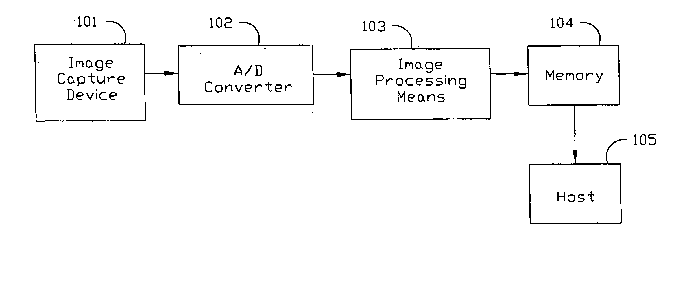
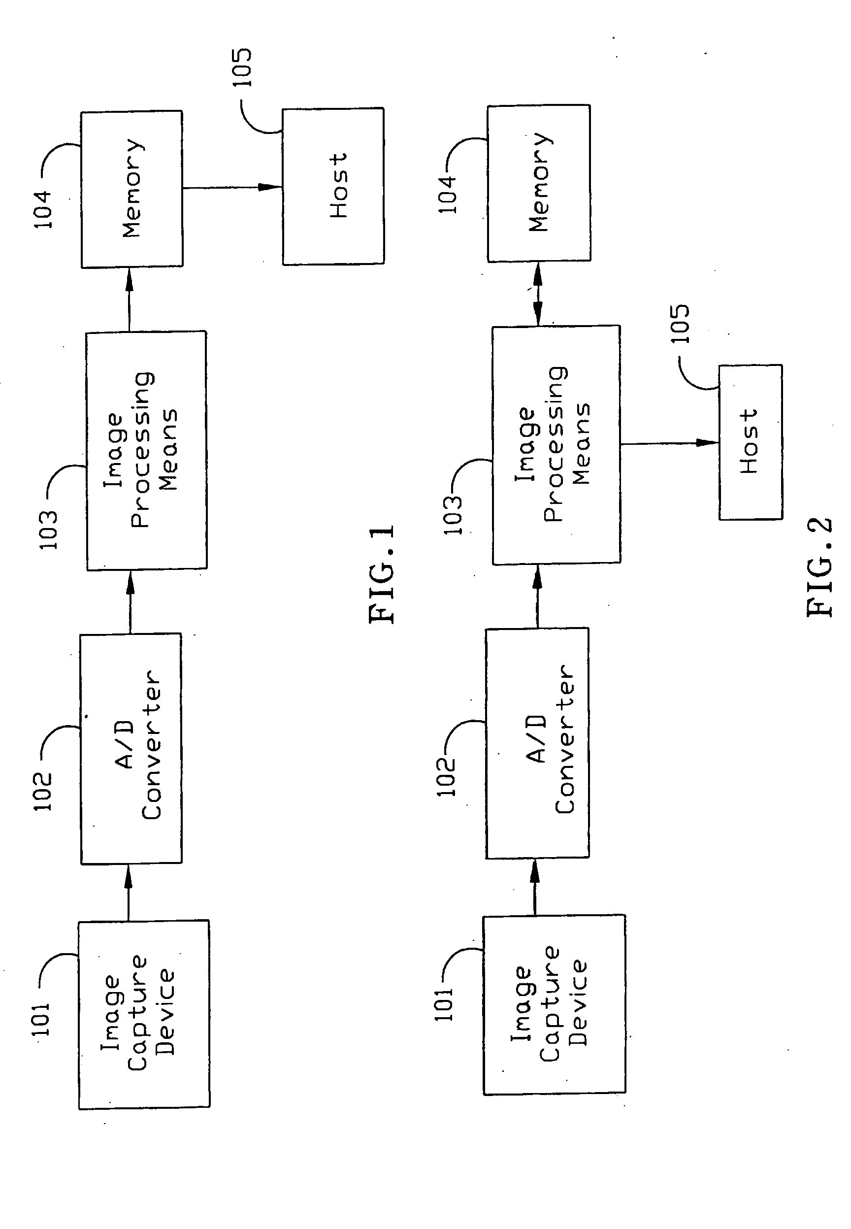
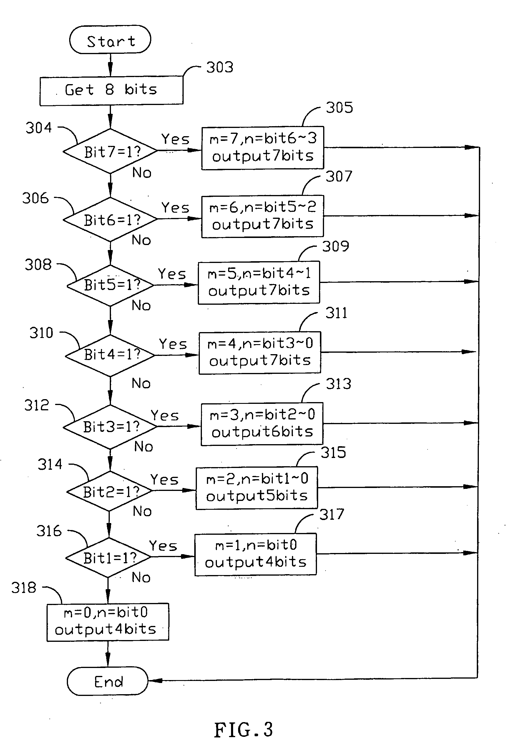
[0022]FIG. 1 is a block diagram of an image processing system implementing image compression methods of the present invention, and FIG. 2 is a block diagram of another image processing system implementing the image compression methods of the present invention. FIG. 3 is a flow chart of one embodiment of the present invention illustrating the present image compression method. FIG. 4 is a flow chart for illustrating an image decompression process of the present invention.

[0023] Initially, referring to FIG. 1, an image is captured from an object by an image capture device 101, e.g. charge-coupled device (CCD), CMOS sensor and the like capable of conve...


PUM


Abstract

An image processing method for facilitating data transmission is provided. An image compression method is performed to convert X-bits binary digital signals to a binary compressed data in a floating-point form of (1.n)*2m. Bit m represents the first bit with logic level “1” of the X-bits binary digital signals, and n represents the bits taken from the X-bits binary digital signals after the bit m. The binary compressed data in the floating-point form of (1.n)*2m is outputted with a sequence of binary number representing a set of (m, n). The latter n bits of the sequence of binary numbers are consisted of the n bits of the X-bits digital signal. Therefore, by the present image compression method, the transmission amount of image data is reduced. The transmission time of image data and the volume of a memory for storing the image data are also reduced.

Description

BACKGROUND OF THE INVENTION [0001] 1. Field of the Invention [0002] The present invention relates to an image processing method, and more particularly, to an image compression method for binary digital signals. [0003] 2. Description of the Prior Art [0004] Without image compression, the transmission of images requires an unacceptable bandwidth in many applications. As a result, methods of compressing images have been the subject of numerous research publications. Image compression schemes convert an image consisting of a two-dimensional array of pixels into a sequence of bits, which are to be transmitted over a communication link. Each pixel represents the intensity of the image at a particular location therein. The transmission link may be an ordinary telephone line. [0005] Consider an image comprising a gray-scale representation of a photograph at a resolution of 1000×1000 lines. Each pixel typically consists of 8 bits, which are used to encode 256 possible intensity levels at the...

Claims


Application Information

Patent Timeline
Patent Type & Authority Applications(United States)
IPC IPC(8): G06K9/36H04N7/26
CPCH04N7/26H04N19/00
Inventor KUO, SHIH-ZHENG
Owner INTELLECTUAL VENTURES I LLC
Learn More