
Method for removing engine deposits from turbie components and composition for use in same

a technology for turbine components and engine deposits, which is applied in the direction of detergent compounding agents, inorganic non-surface active detergent compositions, cleaning using liquids, etc., can solve the problems of oxidation and corrosion of disks/shafts and seal elements, and the resistance is not sufficient to pro

Active Publication Date: 2006-06-29
GENERAL ELECTRIC CO
View PDF26 Cites 9 Cited by
  • Summary
  • Abstract
  • Description
  • Claims
  • Application Information

AI Technical Summary

Benefits of technology

[0014] The method and composition of this invention provides a number of significant benefits for removing such engine deposits from turbine components, especially turbine disks and turbines shafts, that comprise a nickel and / or cobalt-containing base metal. The method and composition of this invention effectively and efficiently remove such engine deposits from turbine components comprising nickel and / or cobalt-containing base metals within a reasonable period of time. The method and composition of this invention also remove such engine deposits in a manner that does not substantially remove or alter the nickel and / or cobalt-containing base metal of the turbine component.

Problems solved by technology

As a result, oxidation and corrosion of the disks / shafts and seal elements have become of greater concern.
They have resistance to oxidation and corrosion damage, but that resistance is not sufficient to protect them at the operating temperatures now being reached.

Method used


Image

  • Method for removing engine deposits from turbie components and composition for use in same
  • Method for removing engine deposits from turbie components and composition for use in same
  • Method for removing engine deposits from turbie components and composition for use in same

Examples


Embodiment Construction

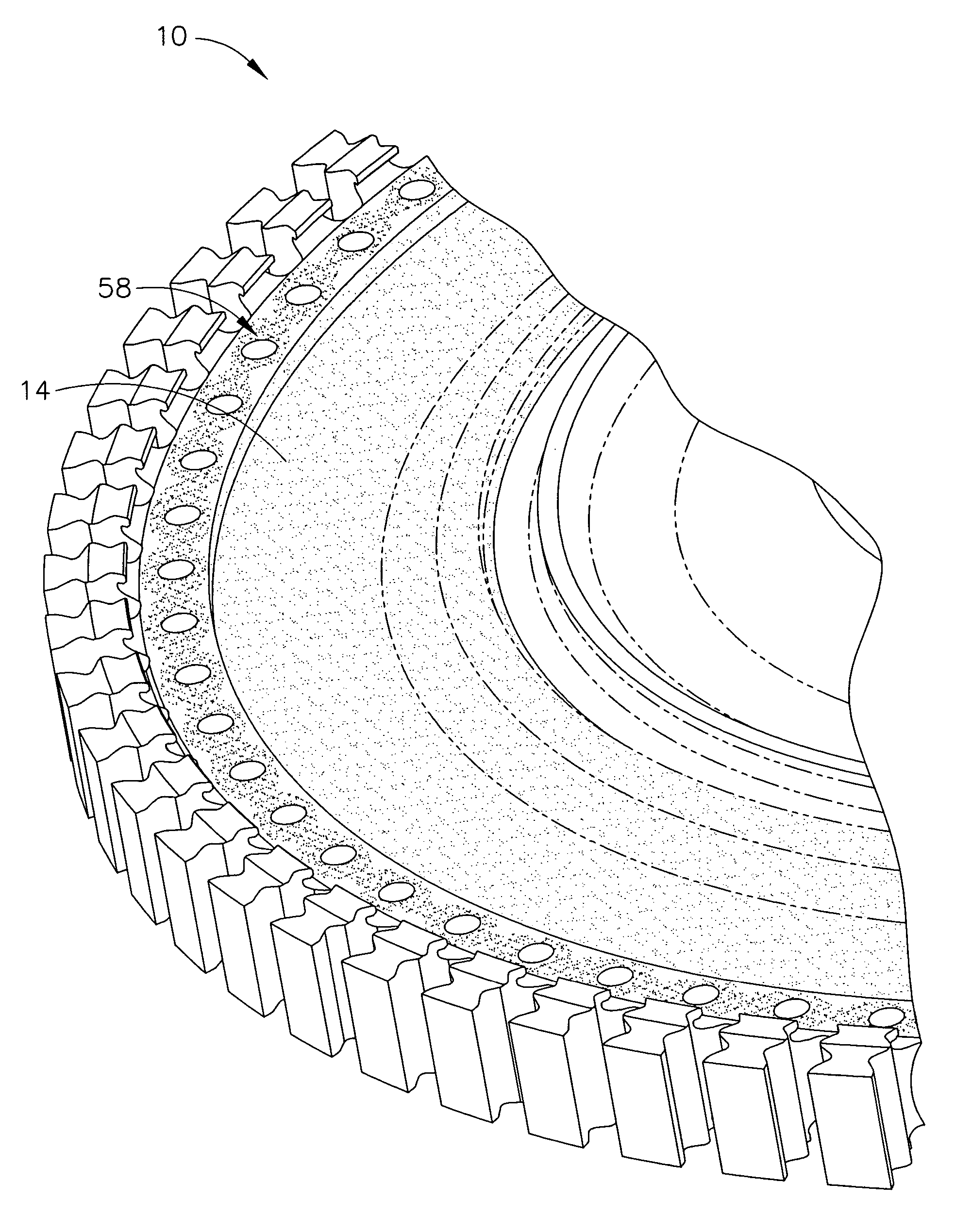
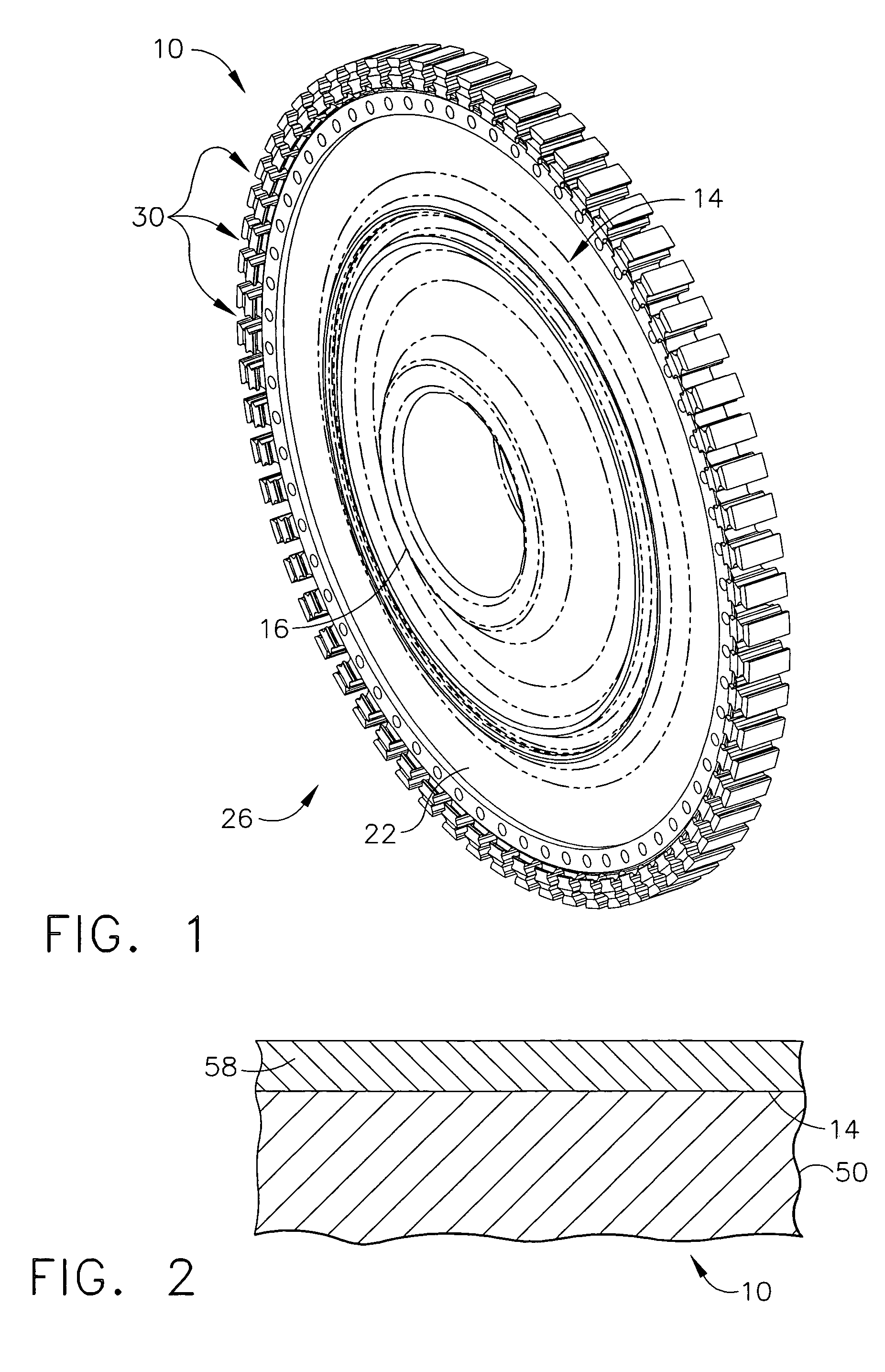
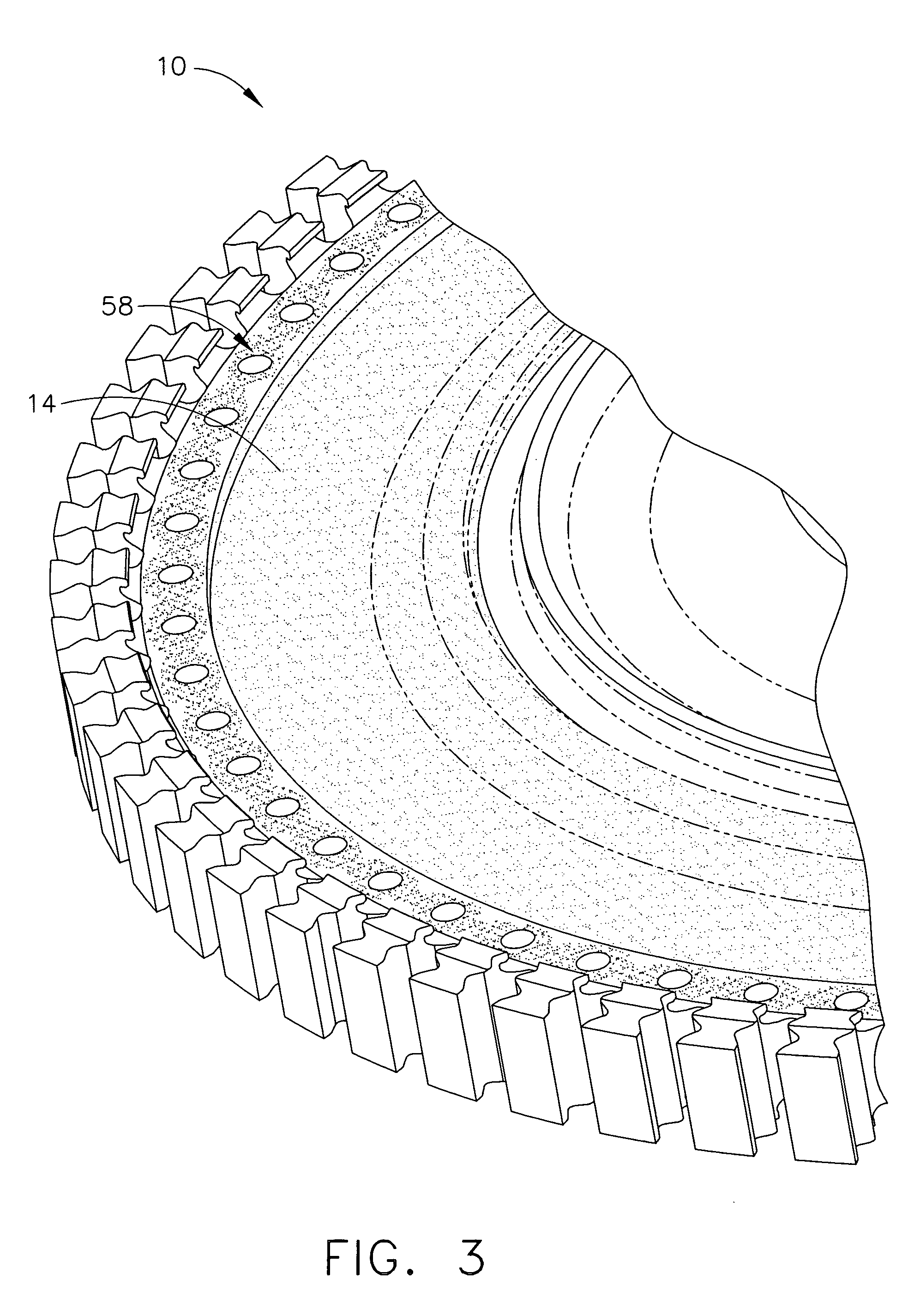
[0021] As used herein, the term “turbine component” refers to a wide variety of turbine engine (e.g., gas turbine engine) parts and components that comprise a nickel and / or cobalt-containing base metal, and which can have engine deposits formed on the surface thereof during normal engine operation that can require removal. These turbine engine parts and components can include turbine disks and shafts, turbine airfoils such as turbine blades and vanes, turbine shrouds, turbine nozzles, combustor components such as liners, deflectors and their respective dome assemblies, augmentor hardware of gas turbine engines, etc. The method and composition of this invention are particularly useful in removing engine deposits from the surfaces of turbine disks and turbine shafts.

[0022] As used herein, the term “nickel and / or cobalt-containing base metal” refers to a base metal that comprises nickel, cobalt, nickel and cobalt alloys, as well as alloys of nickel and / or cobalt with other metals such...


PUM

PropertyMeasurementUnit
Densityaaaaaaaaaa
Densityaaaaaaaaaa
Densityaaaaaaaaaa

Abstract

A method and cleaning composition for removing engine deposits from turbine components, in particular turbine disks and turbine shafts. This method comprises the following steps: (a) providing a turbine component having a surface with engine deposits thereon, wherein the turbine component comprises a nickel and / or cobalt-containing base metal; and (b) treating the surface of the turbine component with a cleaning composition to convert the engine deposits thereon to a removable smut without substantially etching the base metal of the turbine component. The cleaning composition comprises an aqueous solution that is substantially free of acetic acid and comprising: a nitrate ion source in an amount, by weight of the nitrate ion, of from about 470 to about 710 grams / liter; and a bifluoride ion source in an amount, by weight of the bifluoride ion, of from about 0.5 to about 15 grams / liter. The smut that is formed can be removed from the surface of the turbine component in a manner that does not substantially alter the surface thereof.

Description

BACKGROUND OF THE INVENTION [0001] This invention relates broadly to a method for removing engine deposits from turbine components, in particular turbine disks and shafts, using a cleaning composition. This invention further broadly relates to a cleaning composition for use in this method that comprises an aqueous solution comprising a nitrate ion source and a bifluoride ion source. [0002] In an aircraft gas turbine engine, air is drawn into the front of the engine, compressed by a shaft-mounted compressor, and mixed with fuel. The mixture is burned, and the hot exhaust gases are passed through a turbine mounted on the same shaft. The flow of combustion gas turns the turbine by impingement against the airfoil section of the turbine blades, which turns the shaft and provides power to the compressor. The hot exhaust gases flow from the back of the engine, driving it and the aircraft forward. The hotter the combustion and exhaust gases, the more efficient is the operation of the jet en...

Claims


Application Information

Patent Timeline
IPC IPC(8): C23G1/02
CPCC11D3/042C11D3/046C11D3/048C11D7/08C11D7/10C11D7/105C11D11/0041C23G1/10C11D2111/20
Inventor POWERS, JOHN MATTHEWBROOKS, WILLIAM CLARKE
Owner GENERAL ELECTRIC CO
Learn More