

Cyclic structure formation method and surface treatment method
- Summary
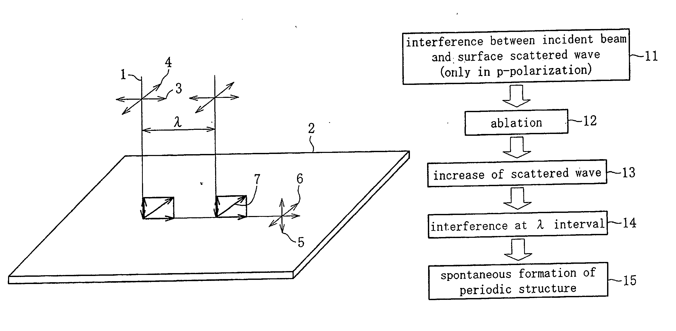
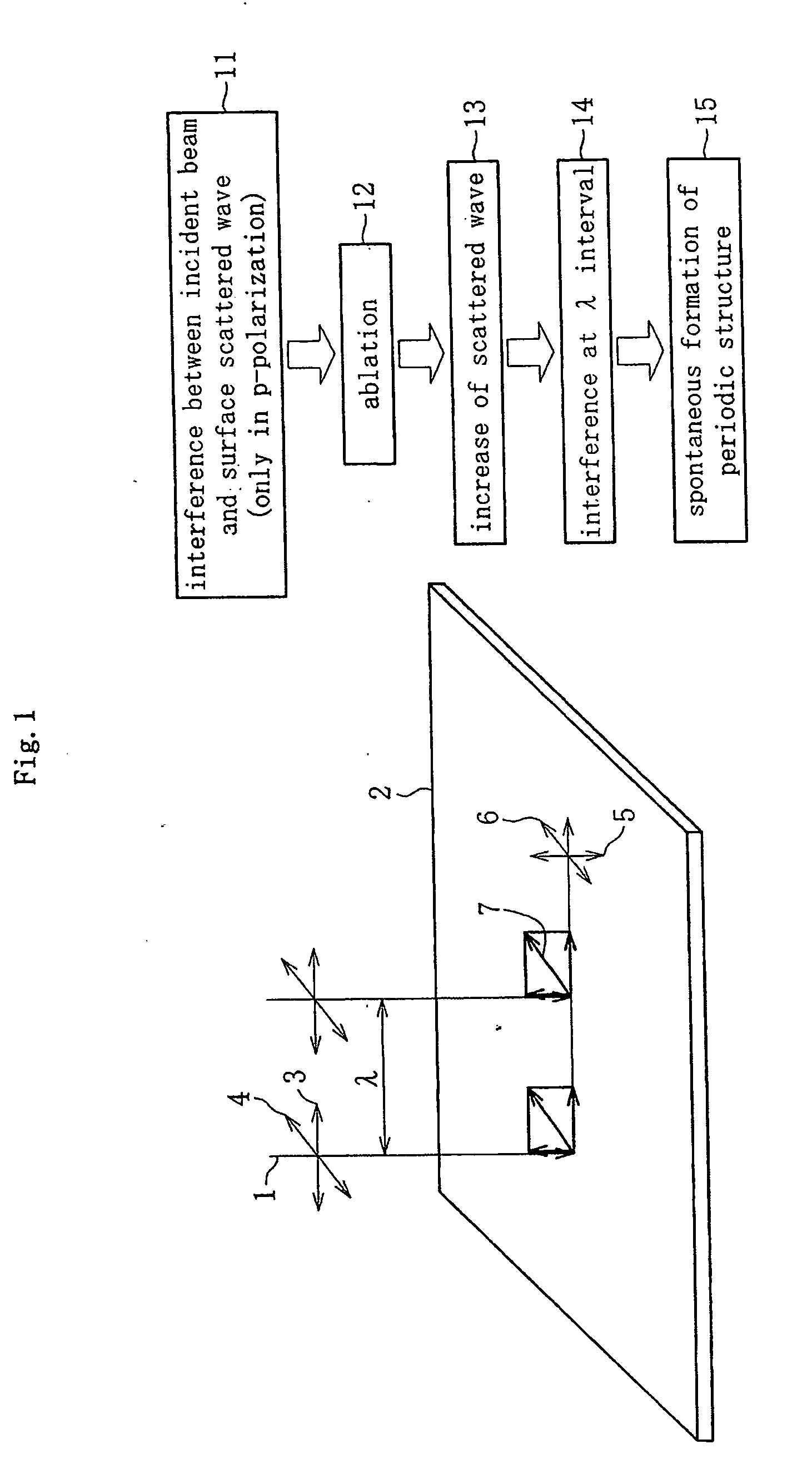
- Abstract
- Description
- Claims
- Application Information
AI Technical Summary
Benefits of technology
Problems solved by technology
Method used
Image

Examples
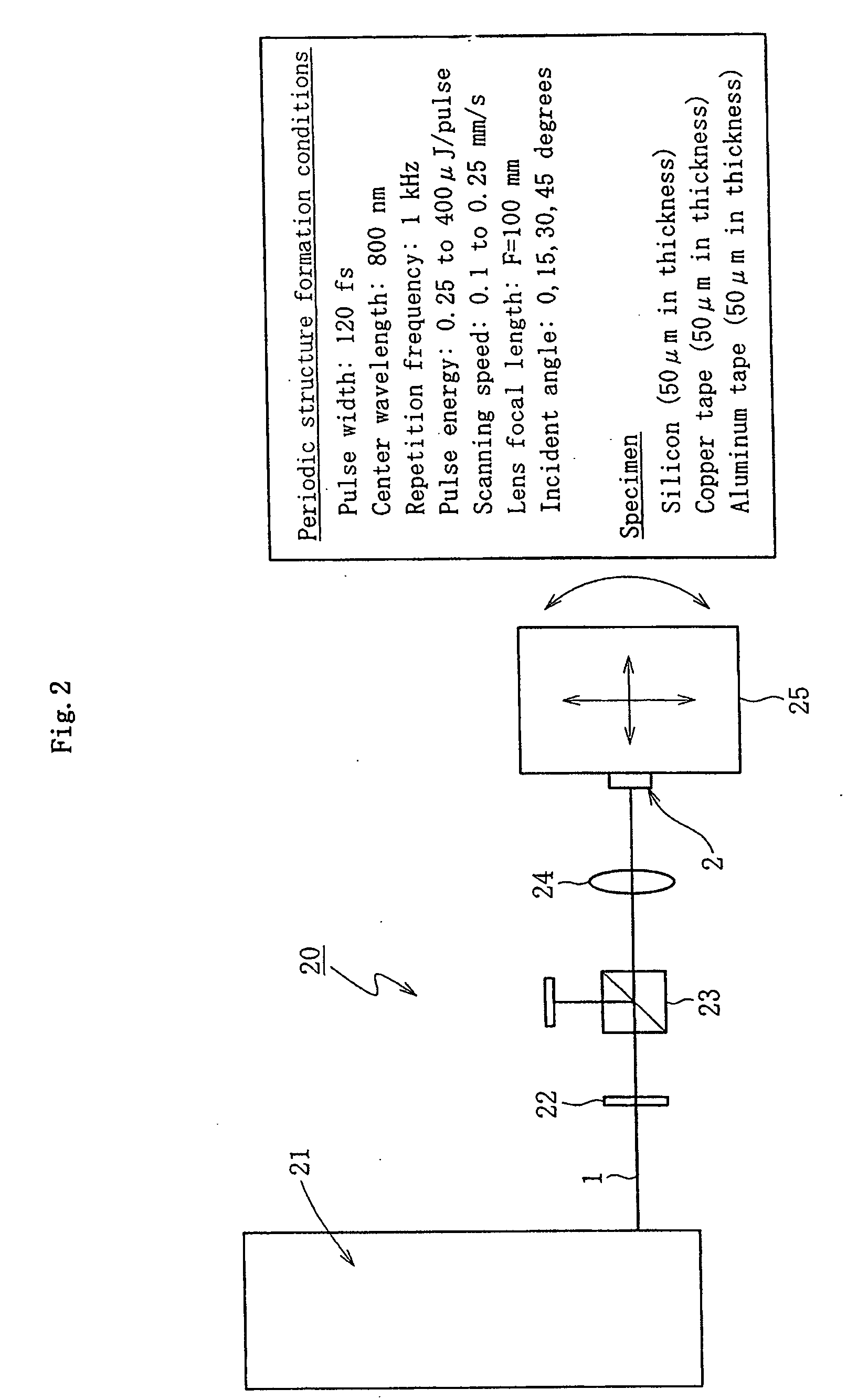
working example
[0133] An effect of the periodic structure according to the present invention to sliding characteristic will be described as under.
[0134]FIG. 17 is a schematic side view showing a sliding test apparatus 60, employed for sliding tests of disc-shaped test pieces on which the foregoing periodic structures are provided. The sliding test apparatus 60 includes a base 61 rotatably supporting a test piece table 63 via a bearing 62, and the test piece table 63 is provided with a recessed portion for retaining a fixed test piece 64 therein. On the base 61, also a pillar 65 is erected, on which a load cell 66 is disposed such that a rotating torque of the test piece table 63 is applied thereto via a cantilever 67. Further, a rotating test piece 68 is disposed so as to oppose the fixed test piece 64, and pure water 69 is filled in the recessed portion of the test piece table 63, so that the pure water 69 is interposed between sliding surfaces of the fixed test piece 64 and the rotating test pi...
PUM
| Property | Measurement | Unit |
|---|---|---|
| Length | aaaaa | aaaaa |
| Volume | aaaaa | aaaaa |
| Area | aaaaa | aaaaa |
Abstract
Description
Claims
Application Information