Remote wire feeder using binary phase shift keying to modulate communications of command/control signals to be transmitted over a weld cable

a technology of phase shift keying and remote control, applied in the field of remote control, can solve the problems of wire feeder and/or welding power source damage, control cable is typically fragile, remote control cable damage,

Active Publication Date: 2006-06-29
ILLINOIS TOOL WORKS INC
View PDF36 Cites 134 Cited by
  • Summary
  • Abstract
  • Description
  • Claims
  • Application Information

AI Technical Summary

Benefits of technology

[0010] The present invention is directed to a remotely controlled welding machine that overcomes the aforementioned drawbacks. A remote control uses phase shift keyed (PSK) modulation to transfer control commands to a welding power source across a weld cable. The information to be communicated to the power source may include welding power source output command information (amperage / voltage control), welding circuit on / off information (power source output contactor control), and power source state control (constant voltage / constant current). A transceiver transmits the control commands of desired welding operational parameters to the power source across a weld cable also designed to carry welding power from the power source to the wire feeder.
[0011] Therefore, in accordance with one aspect of the invention, a welding-type system has a power source designed to deliver power for a welding-type process. The welding system further has a remote device operably connected to receive power from the power source across a weld cable. A communications link is established between the power source and the remote device across the weld cable and is configured to carry control commands at least between the remote device and the power source. In one preferred aspect, the control commands are encoded using narrow-band phase shift key (PSK) modulation.
[0012] In accordance with another aspect, the invention includes a welding system having a power source operable in a power delivery state to deliver power for a welding process and also operable in a stand-by state, wherein the power source is itself powered but does not deliver power for the welding process. The welding system further includes a wire feeder remotely located from the power source and connected to the wire feeder, and designed to receive power for a welding process from the power source across a weld cable. The welding system also has a welding torch that has a trigger and is operably connected to the wire feeder, and designed to deliver consumable wire to a workpiece during the welding process. A communications network is present between the power source and the wire feeder. The communications network is designed to transmit control commands between the power source and the wire feeder across the weld cable. Further, the communications network includes a sensor that detects when the trigger is shifted to a weld start position and upon said detection causes the communications network to transmit a power delivery message to the power source that when received by the power source causes the power source to shift from the stand-by state to the power deliver state such that power for the welding process is delivered from the power source to the wire feeder.

Problems solved by technology

A significant drawback to this cable-based control is that the control cable is typically fragile relative to the welding cables designed to carry high currents at high voltages.
As such, the remote control cable can become damaged by being crushed or snagged from contact with surrounding machines and / or traffic.
This can cause damage to the wire feeder and / or the welding power source if internal power conductors become shorted to signal leads that are connected to sensitive signal level circuitry.
One disadvantage of this system is that the operator has no convenient way to adjust the output of the welding power source to compensate for changes in workpiece thickness and / or fit up.
Another disadvantage of this system is that it requires the presence of a high current DC contactor to de-energize the welding circuit at the wire feeder.
These contactors are large, heavy, costly, and require periodic maintenance to ensure proper and continual operation.
The weld cables, however, can become damaged at a worksite resulting in an unwanted arc being formed between an exposed portion of the cable and an unexpectant ground.
By using pulse width modulated signals to remotely control operation of a power source, the amount of data as well as variability in the types of data that could be transmitted between the wire feeder and a power source is limited.
As a result, absent a DC power supply, the wire feeder cannot be minimally powered so as to communicate with the power source to initiate the welding process.

Method used


Image

  • Remote wire feeder using binary phase shift keying to modulate communications of command/control signals to be transmitted over a weld cable
  • Remote wire feeder using binary phase shift keying to modulate communications of command/control signals to be transmitted over a weld cable
  • Remote wire feeder using binary phase shift keying to modulate communications of command/control signals to be transmitted over a weld cable

Examples


Embodiment Construction

[0023] The present invention will be described with respect to regulation of a power source and a wire feeder of a MIG welding system based on modulated feedback provided from a transceiver remote from the power source to a receiver incorporated within the power source. However, the present invention is equivalently applicable with regulating power sources of TIG, stick, flux cored, and the like welding systems. Moreover, the present invention is also applicable with non-welding, high power systems such as plasma cutters and induction heaters.

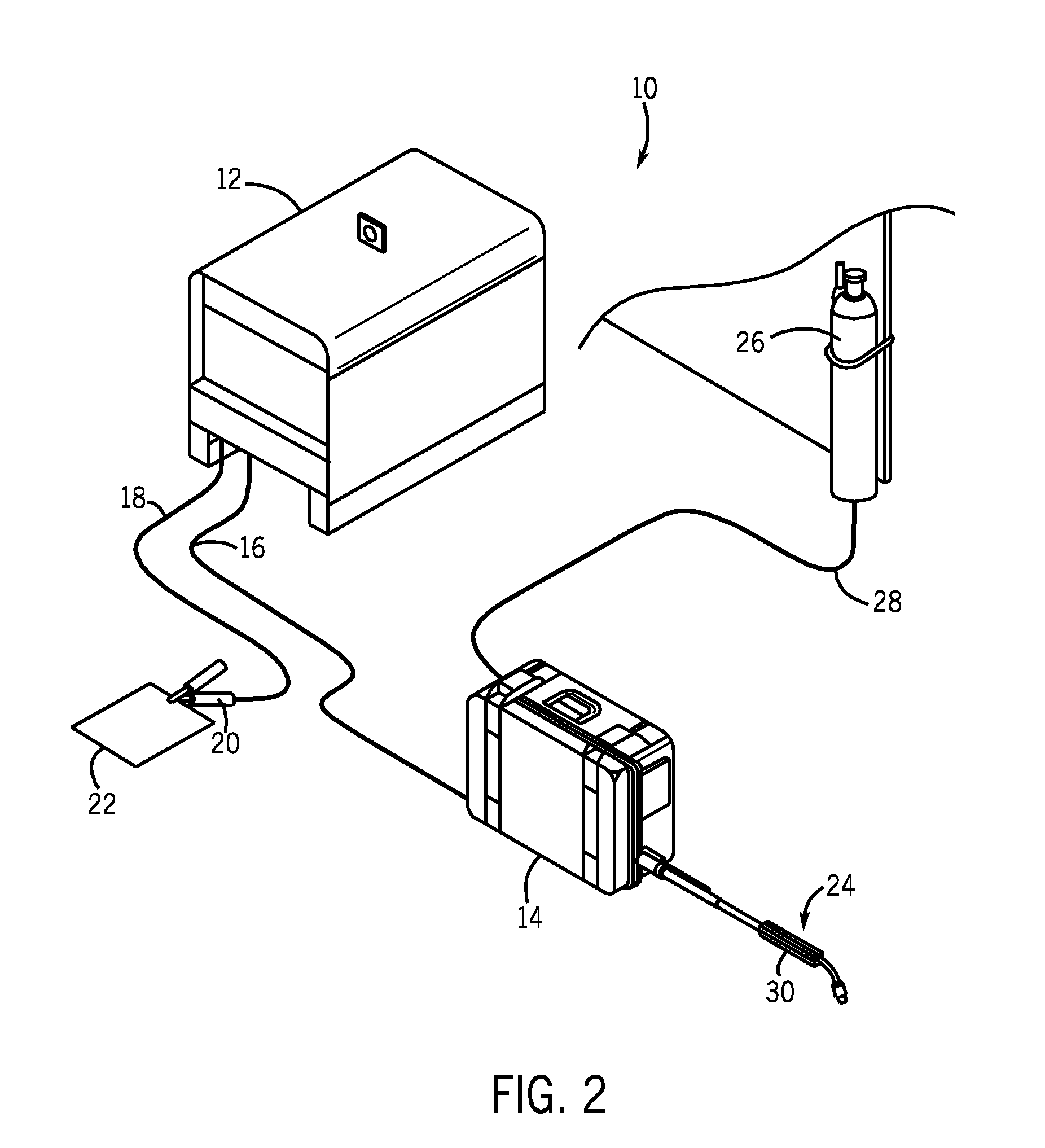
[0024] Referring to FIG. 2, an exemplary MIG welding system 10 includes a welding power source 12 designed to supply power to a wire feeder 14 through a weld cable 16. The power source is designed to run in one of a number of modes including constant voltage (CV) and constant current (CC). Also connected to the power source is a secondary work weld cable 18 that connects the power source to a clamp 20, which holds cable 18 to workpiece 22. Als...


PUM

PropertyMeasurementUnit
frequencyaaaaaaaaaa
frequencyaaaaaaaaaa
lengthaaaaaaaaaa

Abstract

The present invention is directed to a system and method of remotely controlling a welding machine with command signals transmitted to the welding power source across a weld cable connecting the power source to a remote device, such a wire feeder. A transmitter transmits the control commands containing desired welding operational parameters to a receiver disposed in the power source across a weld cable also designed to carry welding power from the power source to the wire feeder.

Description

CROSS-REFERENCE TO RELATED APPLICATION [0001] The present application is a continuation-in-part of U.S. Ser. No. 10 / 709,148 filed Apr. 16, 2004, the disclosure of which is incorporated herein.BACKGROUND OF THE INVENTION [0002] The present invention relates generally to high power systems utilizing a remote power source and, more particularly, to a method and apparatus of remotely controlling a power source designed to deliver power to a remote device. The invention further relates to a power source whose operation is governed by control signals received across a power cable connecting a remote device to the power source. The invention, while not so limited, is believed to be particularly applicable to welding, plasma cutting, and induction heating systems. One exemplary system to which the present invention is applicable is a Metal Inert Gas (MIG) welding system having a power source and a remote wire feeder. [0003] MIG welding, formerly known as Gas Metal Arc Welding (GMAW), combin...

Claims


Application Information

Patent Timeline
Patent Type & Authority Applications(United States)
IPC IPC(8): B23K9/10B23K9/12
CPCB23K9/1087B23K9/125B23K9/124
Inventor OTT, BRIAN L.
Owner ILLINOIS TOOL WORKS INC
Why Eureka
Try Eureka