Dynamic pressure bearing motor

Inactive Publication Date: 2006-06-29
PANASONIC CORP
View PDF3 Cites 3 Cited by
  • Summary
  • Abstract
  • Description
  • Claims
  • Application Information

AI Technical Summary

Benefits of technology

[0025] According to this configuration, since the austenitic stainless acting as a nonmagnetic substance is used, it is possible to increase a degree of cleaning the bearing members. Moreover, since abraded powder of an austenitic stainless is transformed into a magnetic substance, a flow of abraded powder to the outside can be prevented by providing a magnet for trapping abraded powder in the connecting passage between the open end of the bearing and the outside of the motor. With this action, it is possible to provide a hydrodynamic bearing motor which can respond to demands on contamination, cause no flow of abraded powder to the outside of the motor, cause no degradation or the like of motor characteristics, and secure high reliability.
[0026] Further, when the members forming the hydrodynamic radial bearing and the hydrodynamic thrust bearing are made of an austenitic stainless, the magnet for trapping abraded powder has a length of 0.5 mm or longer along the connecting passage, the connecting passage has a width of 2.0 mm or less, and the magnet for trapping abraded powder has a surface magnetic flux density of 0.01 T or higher, so that the hydrodynamic radial bearing and the hydrodynamic thrust bearing

Problems solved by technology

However, during start time from when a stop is made to when the predetermined rotational speed is obtained and during stop time from when the predetermined rotational speed is obtained to when a stop is made, the facing surfaces are brought into contact with each other due to an insufficient hydrodynamic pressure.
When the hydrodynamic bearing motor is used for driving a polygon mirror in a printer, the abraded powder contaminates the polygon mirror and thus adversely affects the quality of printing.
Since magnetic particles (e.g., magnetic powder) are stuck to magnet materials, magnetic materials are hard to improve in a degree of cleaning and have become unusable fo

Method used


Image

  • Dynamic pressure bearing motor
  • Dynamic pressure bearing motor
  • Dynamic pressure bearing motor

Examples


Example

Embodiment 1

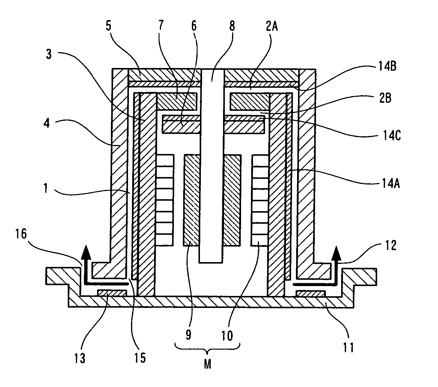
[0039] FIGS. 1 to 3 show Embodiment 1 of the present invention.

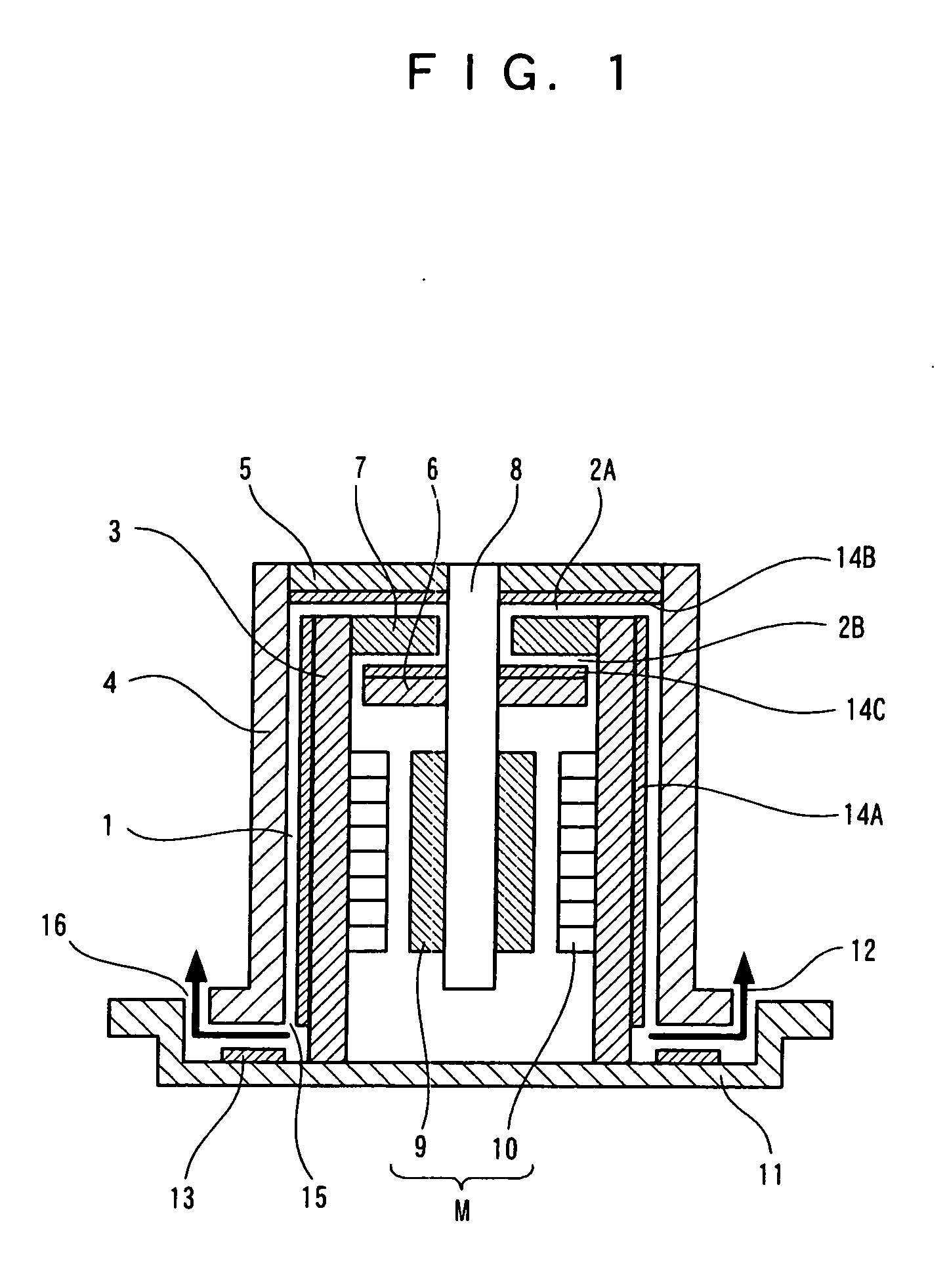
[0040]FIGS. 1 and 2 are sectional views showing a hydrodynamic bearing motor.

[0041]FIG. 1 shows an example where the hydrodynamic bearing motor is applied to a hard disc drive motor. A cylindrical shaft 3 is attached to a base 11 serving as the base of the hydrodynamic bearing motor, and a thrust flange 7 is attached to the upper end of the shaft 3. A stator 10 of a driving motor M is attached to the inner wall of the hollow part of the shaft 3. A sleeve 4 is rotationally attached to the outside of the shaft 3 and a thrust main plate 5 is attached to the upper end of the sleeve 4.

[0042] The sleeve 4 has a pin 8 acting as the axis of rotation and a thrust sub plate 6 is attached to the pin 8 so as to face the thrust flange 7. A ring-shaped magnet 9, which faces a stator 10 and acts as the rotor of the driving motor M, is attached to the outer periphery of the pin 8. The magnet 9 applies a torque to the sle...

Example

Embodiment 2

[0063] FIGS. 4 to 6 show (Embodiment 2) of the present invention.

[0064] In (Embodiment 1), the magnet 13 for trapping abraded powder is provided in the connecting passage 12 between the opening 15 of the sleeve 4 and the external opening 16 of the hydrodynamic bearing motor; whereas in (Embodiment 2) shown in FIG. 4, a labyrinth seal 20 is provided in a connecting passage 12 together with a magnet 13 for trapping abraded powder. Other configurations are similar to those of FIG. 1 and thus the same explanation is omitted.

[0065] With this configuration, the known shielding function of the labyrinth seal 20 prevents a flow of abraded powder during the rotation of a hydrodynamic bearing motor. Although the labyrinth seal 20 loses the shielding function during the stop of the hydrodynamic bearing motor, the abraded powder is stuck to the magnet 13 for trapping abraded powder and thus it is possible to prevent the abraded powder from flowing to the outside.

[0066] As a resu...

Example

Embodiment 3

[0073] In (Embodiment 3), a sleeve 4, a thrust main plate 5, and a thrust sub plate 6 are made of an austenitic stainless, and a shaft 3 and a thrust flange 7 are made of a material harder than the austenitic stainless. Other configurations are similar to those of the hydrodynamic bearing motor described in (Embodiment 1). Coating layers 14A, 14B, and 14C are formed on the outer periphery of the shaft 3 and the upper and lower surfaces of the thrust flange 7.

[0074] According to the present embodiment, a bearing member which is exposed outside a motor and causes a problem of cleaning is made of an austenitic stainless acting as a nonmagnetic material, and the other bearing member is made of a material harder than the austenitic stainless, so that abraded powder is limited to the austenitic stainless. Further, the friction coefficient of a bearing surface can be reduced by changing the hardness of the bearing surface. To be specific, the material can be selected from the...


PUM


Abstract

A magnet (13) for trapping abraded powder is disposed in a connecting passage between an opening of a sleeve and an opening of a hydrodynamic bearing motor, and a shaft (3), a sleeve (4), a thrust flange (7), and a thrust main plate (5) are made of an austenitic stainless. With this configuration, since the austenitic stainless acting as a nonmagnetic substance is used, it is possible to increase a degree of cleaning. Further, abraded powder of the austenitic stainless is transformed into a magnetic substance, and thus a flow of the abraded powder to the outside can be prevented by providing the magnet for trapping abraded powder in the connecting passage between an opening of a bearing and the outside of the motor.

Description

TECHNICAL FIELD [0001] The present invention relates to a hydrodynamic bearing motor mounted in a disc drive device, a laser beam printer and so on which are mainly used in the field of information processing. BACKGROUND ART [0002] Conventionally, ball bearings are used as the bearings of motors for disc drive devices and laser beam printers. In recent years, along with faster rotations of motors in response to demands for faster data transfer and faster printing, hydrodynamic bearings disclosed in, e.g., Japanese Patent Laid-Open No. 2000-352417 and Japanese Patent Laid-Open No. 11-275807 have been used as bearings, instead of conventional ball bearings, to respond to fast rotations of motors. [0003]FIG. 9 shows a conventional hydrodynamic bearing motor disclosed in Japanese Patent Laid-Open No. 2000-352417. [0004] A thrust flange 107 and a shaft 103 are both made of a magnetic material such as iron. A hydrodynamic thrust bearing is constituted of a clearance 102 in which the shaft...

Claims


Application Information

Patent Timeline
IPC IPC(8): H02K7/00H02K5/16B41J2/44F16C17/10F16C33/10F16C33/12F16C33/24F16C33/74G11B19/20H02K5/10H02K7/08
CPCF16C17/10F16C33/107F16C33/74G11B19/2018H02K7/085F16C2370/12
Inventor YAMAMOTO, TAKEYOSHITOKUNO, YASUNORIJYONO, MASAHIROIKEGAWA, TAIZO
Owner PANASONIC CORP
Why Eureka
Try Eureka