Exposure method, substrate stage, exposure apparatus, and device manufacturing method

a technology of substrate stage and exposure method, which is applied in the direction of microlithography exposure apparatus, printers, instruments, etc., can solve the problems of deteriorating the pattern image projected, insufficient focus margin during the exposure operation, and electric leakage of the stage drive system

Inactive Publication Date: 2006-06-29
NIKON CORP
View PDF80 Cites 179 Cited by
  • Summary
  • Abstract
  • Description
  • Claims
  • Application Information

AI Technical Summary

Benefits of technology

[0012] In accordance with the present invention, because the side surface of the substrate is applied with liquid-repellent treatment, penetration of the liquid into, for example, the space between a member (substrate stage) disposed so as to surround the substrate and the side surface of the substrate can be prevented. Thus, penetration of the liquid to the underside surface side of the substrate can be prevented. Furthermore, mixing of bubbles with the liquid, for example, is also prevented, and thus, the edge areas of the substrate can be exposed in a condition that the liquid immersion region is formed well.
[0030] In accordance with the present invention, while suppressing penetration of the liquid to the underside side of the substrate, into the inside of the substrate stage, or into the vacuum system, the substrate can be liquid immersion exposed, and thus devices having a desired performance can be manufactured.

Problems solved by technology

When the depth of focus δ becomes too narrow, it becomes difficult to make the substrate surface coincide with the image plane of the projection optical system, and thus there occurs the possibility that the focus margin during the exposure operation will be insufficient.
By the way, with the above-described related art, there are problems as described below.
However, when, as shown by the schematic of FIG. 27, projection area 100 of the projection optical system is applied to peripheral area (edge area) E of substrate P for the purpose of exposing edge area E of substrate P, the liquid flows out to the outside of substrate P, which leads to the disadvantage that the liquid immersion region is not formed well, thus deteriorating the pattern image projected.
Furthermore, there also arises the disadvantage that the liquid that flowed out causes mechanical parts, etc. in the vicinity of the substrate stage that supports substrate P to rust or causes electric leakage of the stage drive system, etc.
Moreover, if the liquid that flowed out finds its way over to the underside surface of the substrate and penetrates into the space between the substrate and the substrate stage (substrate holder), there also arises the disadvantage that the substrate stage cannot hold the substrate well.
In addition, air bubbles may come to be mixed in the liquid due to the height difference or gap between substrate P and the substrate stage, and, in this case, there arises the disadvantage, for example, that the exposure light is scattered under the influence of the air bubbles or that the pattern does not focus into an image on substrate P because of the bubbles.
Besides, also when the liquid penetrates into the above-mentioned gap, rust or electric leakage may be induced.

Method used


Image

  • Exposure method, substrate stage, exposure apparatus, and device manufacturing method
  • Exposure method, substrate stage, exposure apparatus, and device manufacturing method
  • Exposure method, substrate stage, exposure apparatus, and device manufacturing method

Examples


Embodiment Construction

[0058] Now, referring to the drawings, an exposure apparatus provided with a substrate stage of the present invention will be described.

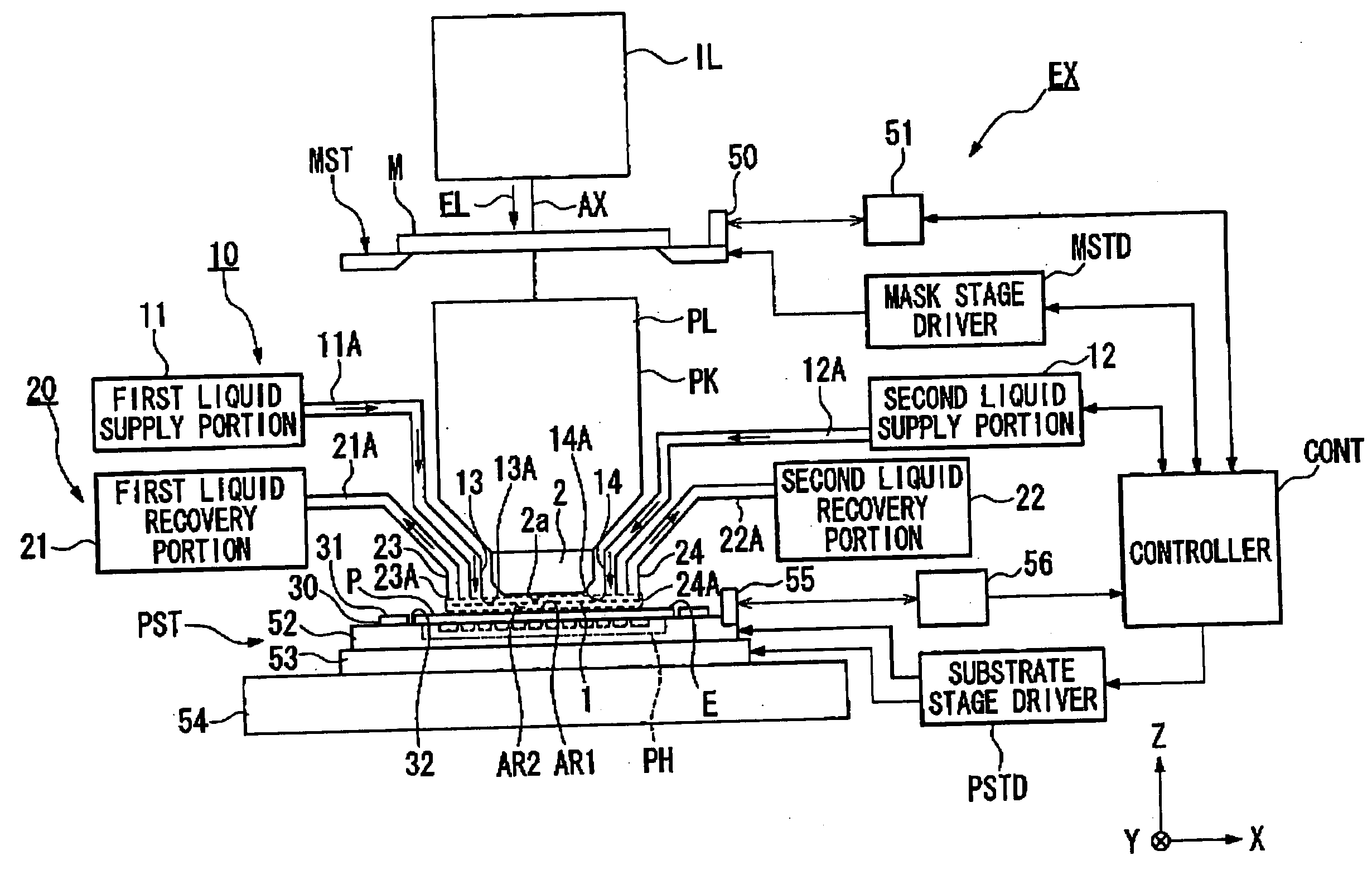
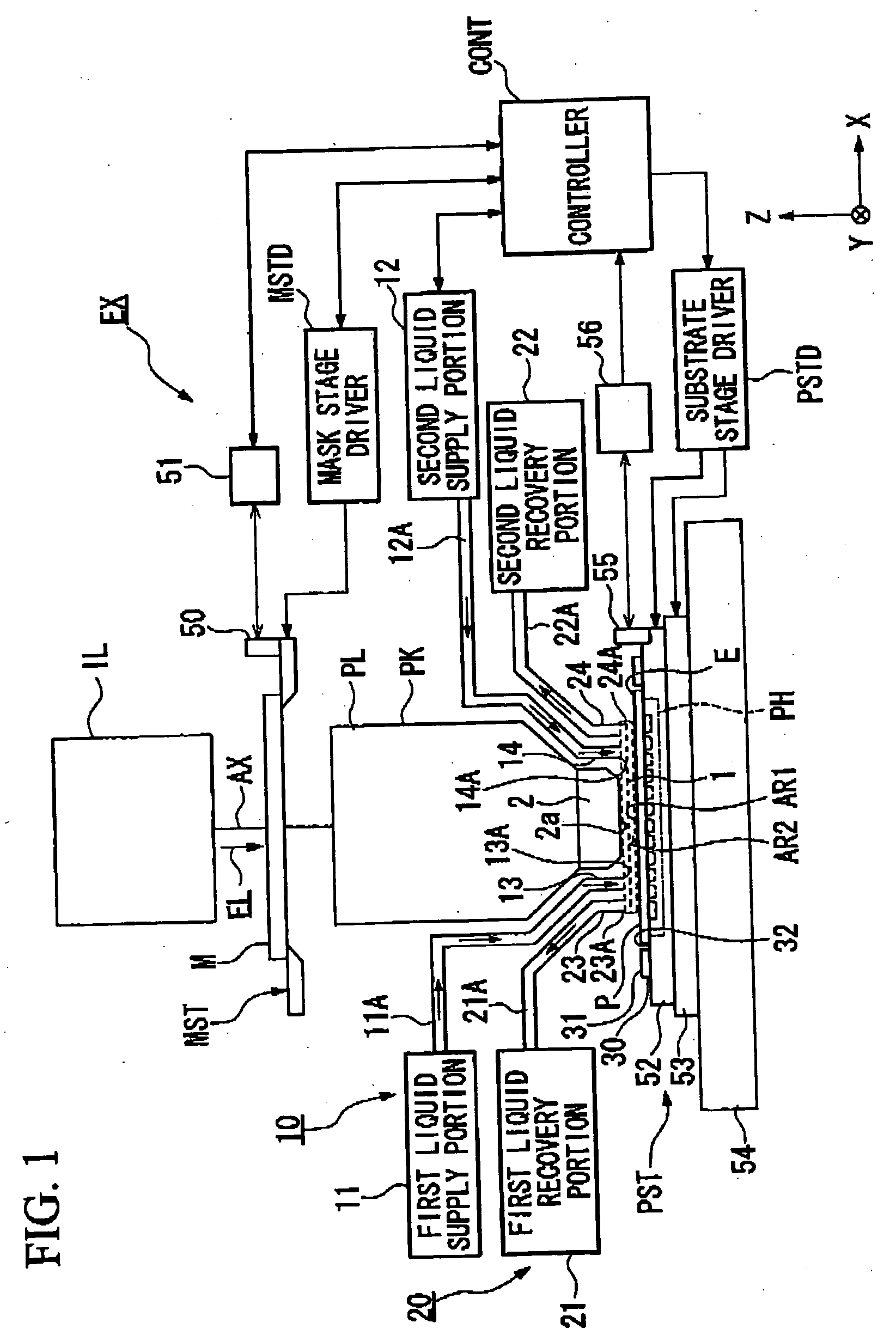
[0059]FIG. 1 is a schematic diagram showing an embodiment of an exposure apparatus of the present invention.

[0060] Referring to FIG. 1, exposure apparatus EX is provided with mask stage MST that supports mask M, substrate stage PST that supports substrate P, illumination optical system IL that illuminates mask M supported by mask stage MST with exposure light EL, projection optical system PL that projection exposes a pattern image of mask M illuminated with exposure light EL onto substrate P supported by substrate stage PST, and controller CONT that controls the overall operation of exposure apparatus EX.

[0061] Exposure apparatus EX of the embodiment is a liquid immersion exposure apparatus, to which a liquid immersion method is applied, with the exposure wavelength being shortened in effect, to improve the resolution and, at the same time, to wi...


PUM

PropertyMeasurementUnit
wavelengthaaaaaaaaaa
refractive indexaaaaaaaaaa

Abstract

In exposing substrate by projecting an image of a pattern onto substrate via projection optical system and liquid, side surface and underside surface of substrate are applied with liquid-repellent treatment. By such a configuration, an exposure method by which when exposing edge areas of the substrate, the exposure can be performed in a condition that a liquid immersion region is formed well and that flowing out of the liquid to the outside of the substrate stage are prevented is provided.

Description

CROSS-REFERENCE TO RELATED APPLICATION [0001] This is a Continuation Application of International Application No. PCT / JP2004 / 008578, filed Jun. 11, 2004, which claims priority to Japanese Patent Application Nos. 2003-169904 (filed on Jun. 13, 2003), 2003-383887 (filed on Nov. 13, 2003), and 2004-039654 (filed on Feb. 17, 2004). The contents of the aforementioned application are incorporated herein by reference.BACKGROUND OF THE INVENTION [0002] 1. Field of the Invention [0003] The present invention relates to an exposure method by which a pattern image is exposed, via a projection optical and a liquid, on a substrate; to a substrate stage that supports a substrate; to an exposure apparatus; and to a device manufacturing method. [0004] 2. Description of Related Art [0005] Semiconductor devices and liquid crystal display devices are manufactured through the so-called photolithography technique, by which a pattern formed on a mask is transferred onto a photosensitive substrate. The exp...

Claims


Application Information

Patent Timeline
Patent Type & Authority Applications(United States)
IPC IPC(8): G03B27/58G03F7/20
CPCG03B27/58G03F7/2041G03F7/70716G03F7/707G03F7/70341
Inventor OWA, SOICHIMAGOME, NOBUTAKAHIRUKAWA, SHIGERUKUDO, YOSHIHIKOINOUE, JIROKOHNO, HIROTAKANEI, MASAHIROIMAI, MOTOKATSUNAGASAKA, HIROYUKISHIRAISHI, KENICHINISHII, YASUFUMITAKAIWA, HIROAKI
Owner NIKON CORP
Why Eureka
Try Eureka