Scanner having spatial light modulator

a scanning scanner and spatial light technology, applied in the field of optical scanning scanners, can solve the problems of inflexible devices and readily scalable, and achieve the effect of high lateral resolution and excellent suppression

Active Publication Date: 2006-06-29
ILLUMINA INC
View PDF73 Cites 74 Cited by
  • Summary
  • Abstract
  • Description
  • Claims
  • Application Information

AI Technical Summary

Benefits of technology

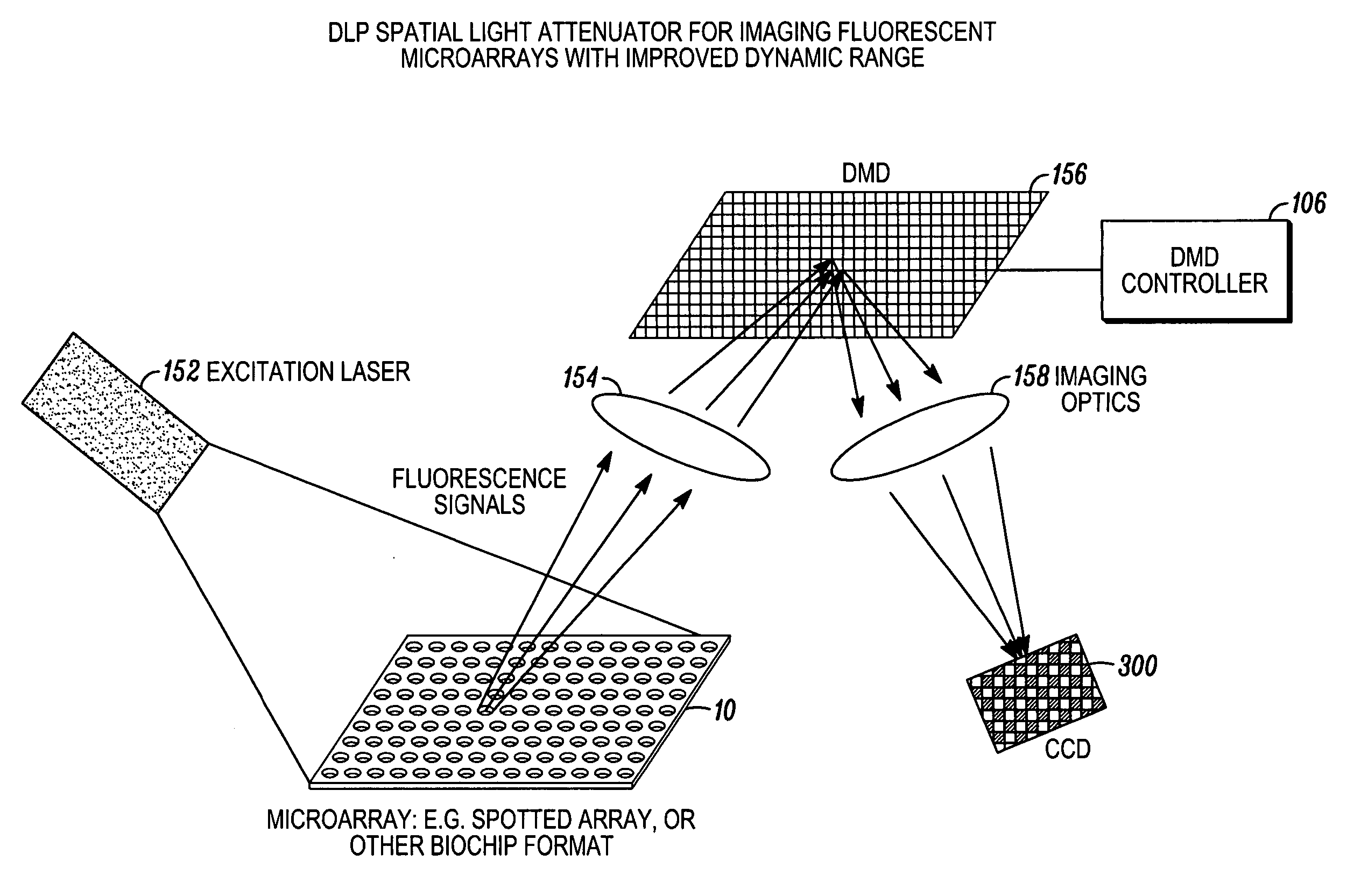
[0014] In imaging biochips / microarrays confocal scanners / readers are commonly used. Confocal optics provide excellent suppression of ‘out-of-focal-plane’ light rejection, and high lateral resolution. The image is often recorded using multiple fluorescence tags that indicate the degree of binding or hybridization of target biomolecules to probes immobilized on the biochip / microarray.
[0015] The present invention features incorporating an adaptive spectral filter into a confocal scanner optical arrangement or other suitable optical device to permit real time control of the fluorescence signal spectrum being monitored. This new arrangement would allow for better balancing of the fluorescence signals in the analysis of the array.

Problems solved by technology

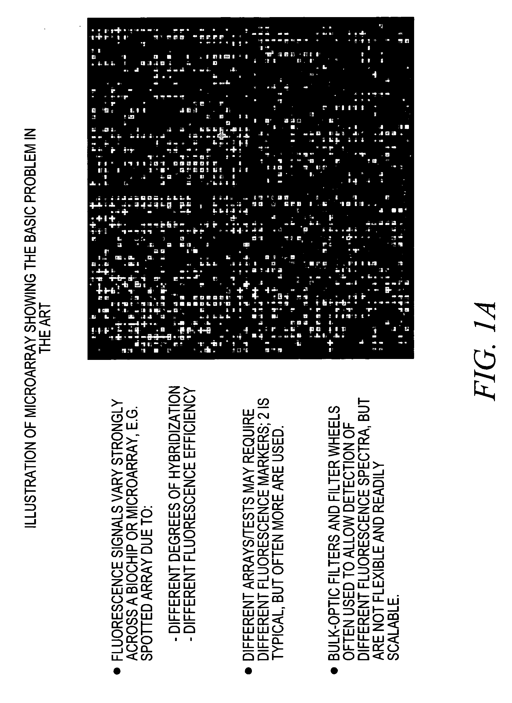
Moreover, different arrays / tests may require different fluorescence markers; two is typical, but often more are used; and bulk-optic filters and filter wheels are often used to allow detection of different fluorescence spectra, but these devices are not flexible and readily scalable.
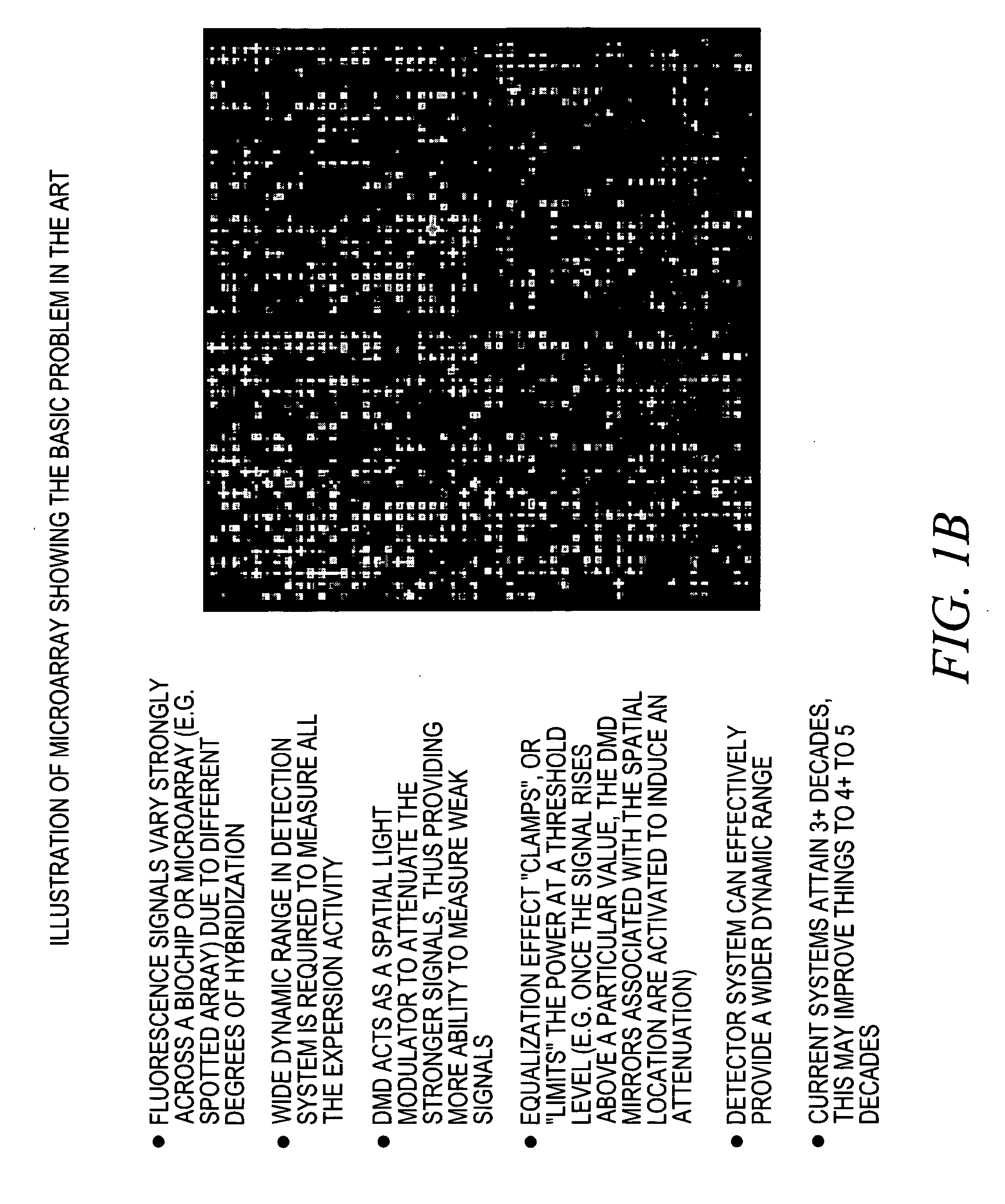
See FIG. 1B, which sets forth another basic problem in the art related to the variation of the fluorescence signals across a micromirror.

Method used


Image

  • Scanner having spatial light modulator
  • Scanner having spatial light modulator
  • Scanner having spatial light modulator

Examples


Embodiment Construction

[0047]FIG. 2 shows a fluorescence detector 20 according to the present invention arranged in relation to a microbead 10 having a grating 12, consistent with that disclosed in patent application Ser. No. 10 / 661,234 (WFVA / CyVERA nos. 714-1.27 / CV 0038A), filed 12 Sep. 2003, application Ser. No. 10 / 661,031 (WFVA / CyVERA nos. 714-1.20 / CV 0039A), also filed 12 Sep. 2003, which are both assigned to the assignee of the instant application and hereby incorporated by reference in its entirety. The microbead 10 forms part of a so-called “bead based” approach for identifying probes that allows the probes to mix without any specific spatial position, which is often called the “random bead assay” approach. In this approach, the probes are attached to the bead 10 instead of a larger substrate like that discussed above so they are free to move (usually in a liquid medium). This approach has an advantage in that the analyte reaction can be performed in a liquid / solution by conventional wet-chemistry ...


PUM

PropertyMeasurementUnit
polarization anglesaaaaaaaaaa
fluorescenceaaaaaaaaaa
optical arrangementaaaaaaaaaa

Abstract

The present invention features incorporating an adaptive spectral filter into a confocal scanner optical arrangement or other suitable optical device to permit real time control of the fluorescence signal spectrum being monitored. This new arrangement would allow for better balancing of the fluorescence signals in the analysis of the array.

Description

CROSS-REFERENCE TO RELATED CASES [0001] This application claims benefit to provisional patent application no. 60 / 628,763 (WFVA / CyVERA nos. 714-1.16 / CV 0031PR), filed Nov. 16, 2004, as well as provisional patent application no. 60 / 628,764 (WFVA / CyVERA nos. 714-1.17 / CV 0030PR), filed Nov. 16, 2004, which are both hereby incorporated by reference in their entirety.BACKGROUND OF THE INVENTION [0002] 1. Technical Field [0003] The present invention relates to an optical scanner; and more particularly, an optical scanner for fluorescence monitoring of an optical device, such as a microarray or biochip (spotted array or other biochip format), or other suitable optical device. [0004] 2. Description of Related Art [0005] A common class of experiments, known as a multiplexed assay or multiplexed experiment, comprises mixing (or reacting) a labeled target analyte or sample (which may have known or unknown properties or sequences) with a set of “probe” or reference substances (which also may hav...

Claims


Application Information

Patent Timeline
Patent Type & Authority Applications(United States)
IPC IPC(8): G01N21/64
CPCG01J3/02G01J3/021G01J3/4406G01N21/6452G01N2021/6471G02B21/0076
Inventor KERSEY, ALANMOON, JOHN A.
Owner ILLUMINA INC
Why Eureka
Try Eureka