
Contrast improving sheet and rear projection screen provided with the same

Active Publication Date: 2006-06-29
DAI NIPPON PRINTING CO LTD
View PDF6 Cites 44 Cited by
  • Summary
  • Abstract
  • Description
  • Claims
  • Application Information

AI Technical Summary

Benefits of technology

[0007] The present invention has been made in view of those problems and it is therefore an object of the present invention to provide a contrast improving sheet to be disposed in front of the front surface, on the viewing side, of a display, such as a rear projection display or a liquid crystal display, capable of increasing contrast and having excellent directivity, and to provide a rear projection screen provided with the same contrast improving sheet.

Problems solved by technology

Although the first optical element is effective to some extent in improving contrast, the first optical element cannot be used as a directional optical element because parallel light rays perpendicularly incident on the first optical element are diffused by the lenticular lens elements.
Therefore, it is very difficult to manufacture the first optical element when the lenticular lenses are arranged at short pitches.
The large amount of light diffusing particles spoils the clearness of images and hence the second optical element cannot be used as a directional optical element.

Method used


Image

  • Contrast improving sheet and rear projection screen provided with the same
  • Contrast improving sheet and rear projection screen provided with the same
  • Contrast improving sheet and rear projection screen provided with the same

Examples


example 1

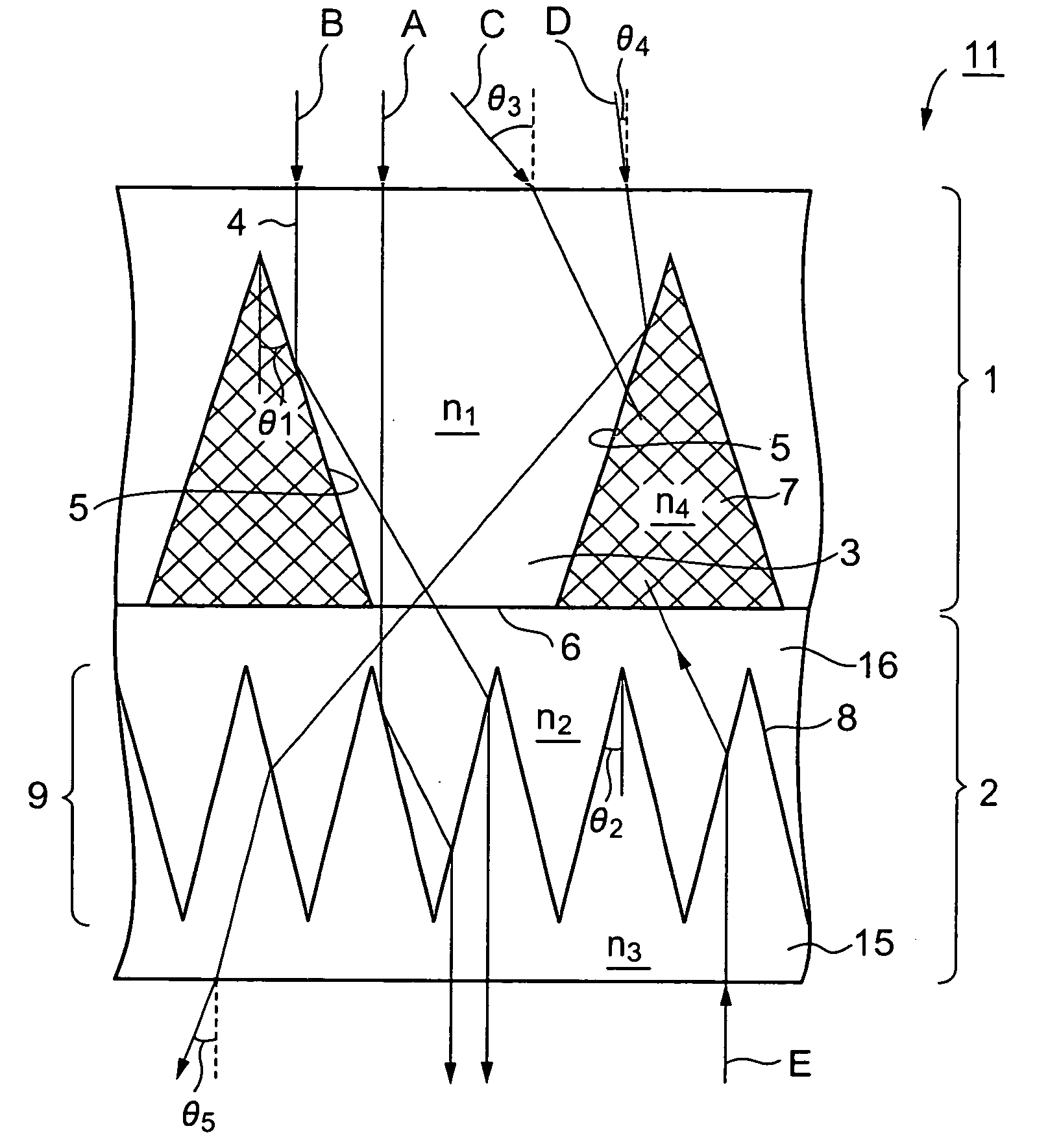
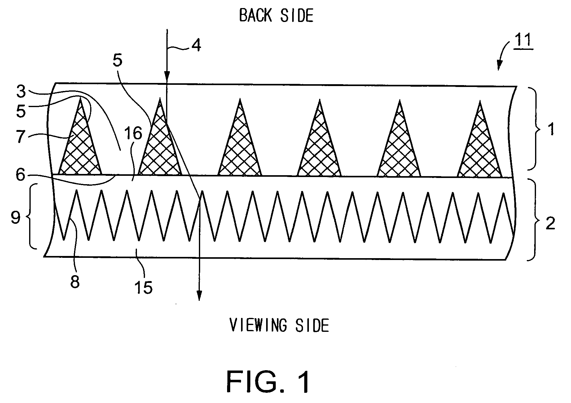
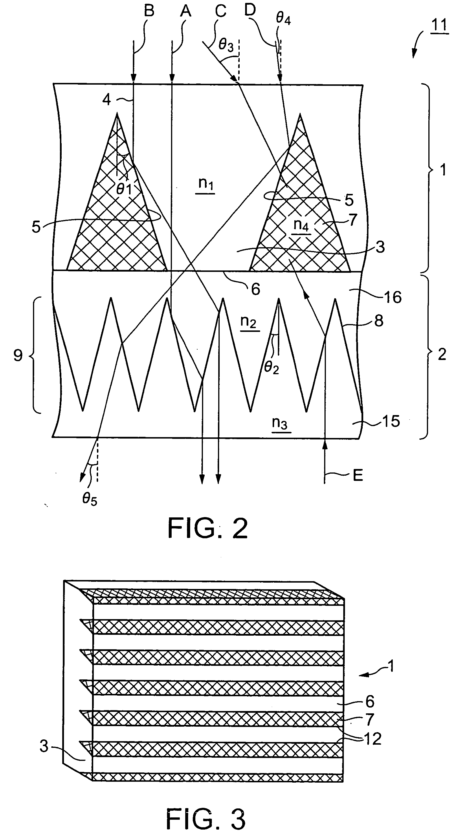
[0080] Protrusions of 0.6 mm in height having a trapezoidal sectional shape were formed of a UV-curable resin having a refractive index n1 f 1.55 after curing on one of the major surfaces of a 50 μm thick PET film having a refractive index of 1.6. The protrusions were arranged at pitches P1 of 0.3 mm. Each protrusions had a flat facet of 0.169 mm in width and total-reflection facets inclined at an inclination angle θ1, of 8°. light absorbing layers were formed by filling up V-grooves between the adjacent protrusions having the trapezoidal sectional shape with a light absorbing material prepared by dispersing black beads having a mean particle size of 6 μm in a acrylic coating material having a refractive index n4 of 1.49 to form a first optical functional element.

[0081] Protrusions of 135 μm in height having a triangular sectional shape were formed of a resin produced by modifying an acrylic resin and having a refractive index n3 of 1.48 on one of the major surfaces of a 1.5 mm thi...

example 2

[0087] A contrast improving sheet in Example 2 was fabricated by the same method as that of forming the contrast improving sheet in Example 1 and using the same materials as those used for forming the contrast improving sheet in Example 1, except that protrusions of a first optical functional element and a back part, contiguous with the first optical functional element, of a second optical functional element were formed of the same resin having a refractive index of 1.55, and a front part, apart from the first optical functional element, of the second optical functional element was formed of a silicone resin having a refractive index of 1.43.

(Evaluation)

[0088] The contrast improving sheet in Example 2 was evaluated.

[0089] A rear projection television set having a projection distance of 300 mm, a projection angle of 65° and a screen size of 60 in. was used as a test rear projection television set. the test rear projection television set was provided with a conventional rear proje...

example 3

[0091] A contrast improving sheet in Example 3 was fabricated similarly to the contrast improving sheet in Example 2, except that the contrast improving sheet in Example 3 included a first optical functional element having protrusions of 0.126 mm arranged at pitches P1 of 0.063 mm and a second optical functional element having protrusions of 60 μm arranged at pitches P2 of 18 μm (P1 / P2=3.5).

(Evaluation)

[0092] The contrast improving sheet in Example 3 was evaluated.

[0093] The contrast improving sheet in Example 3 was combined with a liquid crystal monitor of 15 in. in screen size included in a personal computer (PC). Images displayed on the screen of the liquid crystal monitor were observed through the contrast improving sheet in Example 3. First and second optical functional elements of the contrast improving sheet were laminated and the contrast improving sheet was incorporated into the liquid crystal monitor as shown in FIG. 6.

[0094] The liquid crystal monitor reflected nothi...


PUM


Abstract

A contrast improving sheet to be disposed on the viewing side of a display, such as a rear projection display or a liquid crystal display, to display images in high contrast and in excellent directivity, and a rear projection screen provided with the contrast improving sheet are provided. A contrast improving sheet 11 includes a first optical functional element 1 and a second optical functional element 2 disposed on the viewing side of the first optical functional element 1. The first optical functional element 1 is provided with a plurality of protrusions 3 arranged in a direction or distributed in a plane. Each of the protrusions 3 has a pair of opposite total-reflection facets 5 for totally reflecting image light rays substantially perpendicularly incident on the entrance surface and a flat facet 6 extending between the front edges, on the side of the exit surface, of the pair of opposite total-reflection facets 5. Light absorbing layers 7 are formed in V-grooves between the adjacent protrusions 3. The second optical functional element 2 is provided with a light path correcting layer 9 for correcting light paths followed by the image light rays totally reflected by the total-reflection facets 5 of the protrusions 3 such that the image light rays are emitted through the exit surface substantially perpendicularly to the exit surface. The light path correcting layer 9 has a plurality of inclined planes 8 inclined in opposite directions, respectively, and the inclined planes 8 inclined in opposite directions are arranged alternately.

Description

TECHNICAL FIELD [0001] The present invention relates to a contrast improving sheet to be disposed on the viewing side of a display, such as a rear projection display, a liquid crystal display, a plasma display or a CRT, and to a rear-projection screen provided with the same contrast improving sheet. The term “contrast improving sheet” is used in this specification to signify an optical sheet for suppressing decrease in contrast in images displayed by a display due to external light and stray light to improve contrast in images displayed by the display. BACKGROUND ART [0002] There have been proposed various techniques for optimizing viewing angle of a display, such as a rear projection display or a liquid crystal display, and improving contrast in images displayed by the display so that the viewers are able to recognize images clearly. [0003] More concretely, a previously proposed first optical element is provided with lenticular lenses, namely, light diffusing elements, on its back ...

Claims


Application Information

Patent Timeline
IPC IPC(8): G03B21/56G02B3/00G02B3/08G02B5/00G02B5/02G02B5/04G02B5/22G02B17/00G02B27/00G02F1/13G02F1/1335G02F1/13357G03B21/62G03B21/625
CPCG02B17/006G02B27/0018G02F1/133524G02F2001/133607G03B21/62G02F1/133607
Inventor WATANABE, HITOMUHONDA, MAKOTO
Owner DAI NIPPON PRINTING CO LTD
Learn More