Echo detector having correlator with preprocessing

a detector and preprocessing technology, applied in the field of echo detectors with correlators, can solve the problems of ec as a system rapidly becoming unstable, undesirable effects such as distortion, or additional unpleasant sounds, and achieve the effects of reducing the number of multiplications, and enhancing correlation peaks

Inactive Publication Date: 2006-06-29
TECTEON
View PDF3 Cites 40 Cited by
  • Summary
  • Abstract
  • Description
  • Claims
  • Application Information

AI Technical Summary

Benefits of technology

[0023] This feature helps enables the computational load to be kept low, by reducing the number of multiplications.
[0024] As a preferred additional feature, the characteristic patterns can be based on zero crossings of the respective signal. This can also enable the correlation peaks to be enhanced.
[0025] As a preferred additional feature, the characteristic patterns can be based on auto correlation functions of the respective signal. This can also enable the correlation peaks to be enhanced.
[0026] As a preferred additional feature, the characteristic patterns can be based on pitch. An advantage of using pitch for the correlation is that it can enable a more accurate and reliable detection of the echo. In particular, the detection can be more independent of signal level, more robust in the presence of noise. Alternatively, the correlation update rate can be reduced further, since human pitch normally does not change as rapidly as the entire signal. Typically it will not change over periods of 25-60 msecs This can outweigh the additional computational load and delay involved in determining the pitch.

Problems solved by technology

These requirements make the design very demanding.
In such case if the echo tails are delayed beyond the scope of the EC capability, and the EC is not switched off temporarily, it could have very undesirable effects such as distortion, or additional unpleasant sounds, such as howling.
In other words the EC as a system may rapidly become unstable.
The known methods do not achieve these or do not achieve them with sufficiently low computational load, or short processing time, with appropriate accuracy and reliability.

Method used


Image

  • Echo detector having correlator with preprocessing
  • Echo detector having correlator with preprocessing
  • Echo detector having correlator with preprocessing

Examples


Embodiment Construction

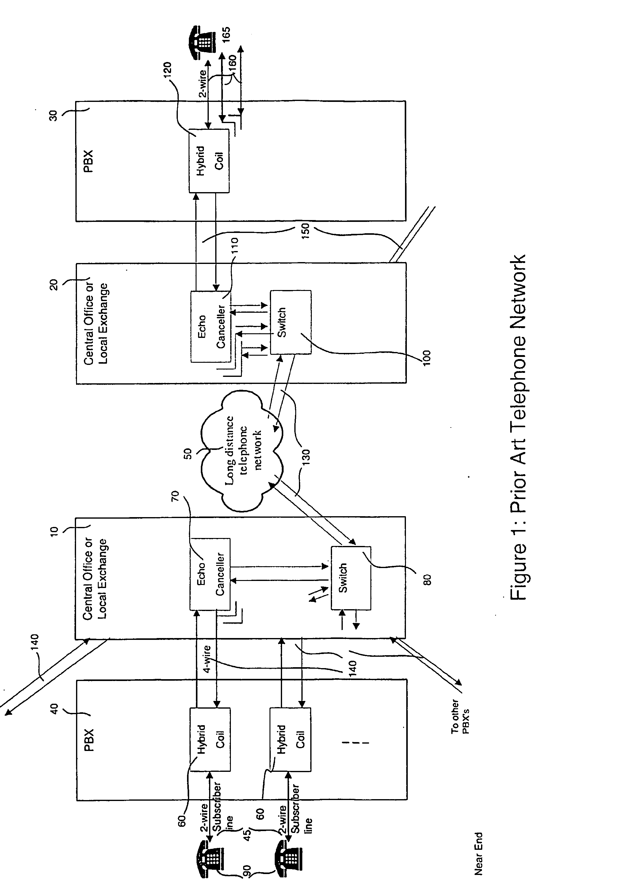
[0057]FIG. 1, Showing How Echo Cancellers are used in Conventional Telephone Networks

[0058]FIG. 1 shows an application of the echo canceller of the invention in a conventional telephone network. In this figure, a long-distance telephone network 50 is shown, for making a telephone call from one subscriber to another. For convenience, one side of the network is denoted the near end, and the other side is denoted the far end. A subscriber's handset 90 is coupled to a private branch exchange (P B X) by a 2-wire subscriber line 45. In the P B X, a hybrid coil 60 is used to convert between the two wire subscriber line and a 4-wire line to the Central Office or local exchange 51. The conversion to 4-wire enables the voice signals in two directions to be a separated, which is useful for digitising and further processing. Each P B X may support tens or hundreds of subscribers, and will have sufficient hybrid coils according to how many calls are to be supported simultaneously.

[0059] Connec...


PUM


Abstract

An echo detector correlates between an incoming signal an echo signal to determine echo delay. A preprocesssor extracts a characteristic pattern such as a binary pattern derived by thresholding an averaged power of each signal. This pattern is down sampled then used for the correlation, and delay is deduced from peaks in the correlation. Advantages include reduced computational load, or larger correlation window size, because the characteristic pattern is easier to correlate. The quantising can enhance the correlation peaks, and the averaging can limit the number of transitions, to give more robustness to noise. An echo canceller has a coarse echo delay estimator and a fine echo delay estimator. The coarse estimated delay is used to adjust a delay detection range of a fine delay detector having a narrow range. The output of the fine detector is used to adjust or suppress the adaptive echo canceller.

Description

FIELD OF THE INVENTION [0001] The invention relates to methods and apparatus for detecting delays in echoes, to echo cancellers having such apparatus, to central offices having such echo cancellers for use in telecommunications networks, to methods of providing telecommunications services using the above, to corresponding software and to systems incorporating the above, and corresponding methods. BACKGROUND [0002] There are various known signal processing methods for determining a delay of an echo (also termed echo ranging). As well as being useful for echo cancellation, it is useful in a wide variety of applications such as geology, oceanometry, mobile GSM and CDMA, radar target locating, underwater object location, and in particular at receivers of antenna arrays when multi-path reflections are detected. For the different applications, the principles are the same but implementation requirements or constraints may differ. In case of the geology or seismology, for mapping undergroun...

Claims


Application Information

Patent Timeline
Patent Type & Authority Applications(United States)
IPC IPC(8): H04M9/08H04B3/23
CPCH04B3/23
Inventor AHMADI, MASOUD
Owner TECTEON
Why Eureka
Try Eureka