Cell separation apparatus

a cell sorting and cell technology, applied in the field of cell sorting apparatus, can solve the problems of sample not being able to be directly observed, cell damage, and drawback of cell sorter

Inactive Publication Date: 2006-06-29
ON CHIP CELLOMICS CONSORTIUM
View PDF5 Cites 29 Cited by
  • Summary
  • Abstract
  • Description
  • Claims
  • Application Information

AI Technical Summary

Problems solved by technology

However, this technique has many drawbacks that it is expensive and necessitates a large apparatus, a high electric field such as several thousand bolts and a large amount of samples, the cell is possibly damaged in the process of preparing droplets, the sample cannot directly be observed, etc.
However, this cell sorter has a drawback that the speed of response to observation means when separating a sample is slow.

Method used


Image

  • Cell separation apparatus
  • Cell separation apparatus
  • Cell separation apparatus

Examples


Embodiment Construction

[0039] Now, one embodiment of a cell separation apparatus of the present invention will be described but the present invention is not to be restricted in any way to this embodiment.

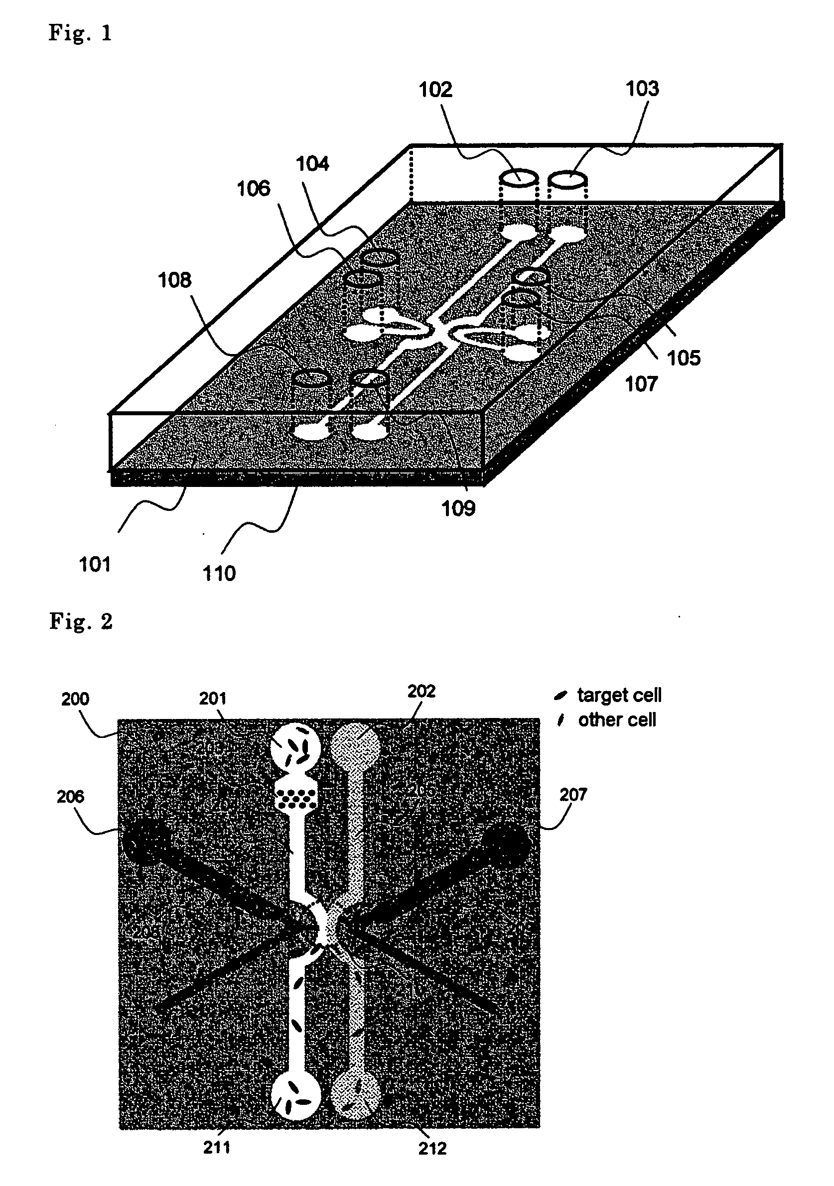
[0040]FIG. 1 shows schematically one embodiment of the systematic construction of a cell separation apparatus (cell sorter) of the present invention. This cell sorter is constructed in the form of a channel within a chip 101. The chip has a glass base plate 110 adhesively bonded at its bottom, on which glass base plate is formed a micro-channel. Then, the thickness of the glass base plate is made as thin as possible in order to conduct an optical measurement. For example, when an object lens is used which has a numerical aperture of 1.4 and a factor of 100, it is desirable that the glass base plate has a thickness of 0.2 mm or less. On the top surface of the chip 101, a hole 102 for introducing a sample solution containing a cell into a micro-channel, a hole 103 for introducing a cell-free solution into ...


PUM

PropertyMeasurementUnit
electric voltageaaaaaaaaaa
distanceaaaaaaaaaa
distanceaaaaaaaaaa

Abstract

A cell separation apparatus comprises a means for moving a cell within a cell separating space by applying an electrical voltage to cells in the cell separating space using gel electrodes, and channels for separating and discharging the cell, which thus does not damage a cell sample and prevents the exhaustion of an electrode due to its electrolysis.

Description

FIELD OF THE INVENTION [0001] The present invention relates to a cell separation apparatus (or cell sorter). BACKGROUND OF THE INVENTION [0002] It is an important technique in biological and medical analyses to separate and recover a specific cell in a culture solution. When a cell can be separated from other cells by a difference in specific gravity of the cell, the cell can be obtained by a velocity sedimentation method. However, when there is substantially no difference among cells in such a case to distinguish an unsensitized cell and a sensitized cell, it is necessary to separate the cells one by one on the basis of information obtained by dyeing them with a fluorescent antibody or information visually obtained by human eyes. [0003] As an example of this technique, there is a cell sorter. Cell sorter is a technique wherein fluorescent dye-treated cells are isolated in one cell unit and dropped into charged droplets, and a high electric field is applied to the charged droplets d...

Claims


Application Information

Patent Timeline
Patent Type & Authority Applications(United States)
IPC IPC(8): C12M1/00C12N5/06C12M1/42
CPCB01L3/502761B01L2300/0681B01L2400/0421B01L2400/043B01L2400/0439B01L2400/086C12M47/04
Inventor YASUDA, KENJITAKAHASHI, KAZUNORI
Owner ON CHIP CELLOMICS CONSORTIUM
Why Eureka
Try Eureka