Data transmission method, base station and transmitter for compensating for non-linearities in a transmission chain

a transmission chain and data transmission technology, applied in the field of data transmission methods, a base station and a transmitter in a telecommunication system, can solve the problems of high linearity of the sub-amplifier, inapplicability of wide-band transmitter techniques, and difficult feedback control of radio frequency, so as to improve linearization and keep the number of independent variables low

Inactive Publication Date: 2006-06-29
NOKIA SOLUTIONS & NETWORKS OY
View PDF6 Cites 11 Cited by
  • Summary
  • Abstract
  • Description
  • Claims
  • Application Information

AI Technical Summary

Benefits of technology

[0019] The method and system of the invention provide several advantages. For instance, in lookup tables (LUT) used in the prior-art solutions each entry is an independent variable. As the dimensions of the distortion model increase, the dimensions of the variable space grow exponentially which makes a high-dimensional model very difficult to implement in practice, because the number of adaptation rounds increase. A preferred embodiment of the invention enables the use of higher-dimensional models which can better follow the changes in the system. A preferred embodiment of the invention allows utilization of a larger number of model features compared to the prior-art solutions, while keeping the number of independent variables low.
[0020] In addition, another preferred embodiments of the invention further improves the linearization, because the frequency domain distortion which usually appears in analogue circuits is also compensated.

Problems solved by technology

Unfortunately, high-power radio-frequency amplifiers tend to be non-linear devices and therefore they in many cases cause distortion.
However, feedback control on radio-frequencies becomes difficult because of realtime feedback circuit implementation.
This technique is not applicable to wide-band transmitters, due to its rather narrow frequency band.
The problem is that the linearity of the sub-amplifier must be high and this can decrease the overall power efficiency.
The problem is that the compensating performance deteriorates if the amplifier parameters deviate from the designed values.
The problem in the prior-art solutions is, however, that the linearization of distorted signals is inadequate.
Typically pre-distortion parameters are stored in a look-up table, but this approach easily enlarges the memory size and creates quantization noise, because parameter values typically differ from each other by predetermined steps.

Method used


Image

  • Data transmission method, base station and transmitter for compensating for non-linearities in a transmission chain
  • Data transmission method, base station and transmitter for compensating for non-linearities in a transmission chain
  • Data transmission method, base station and transmitter for compensating for non-linearities in a transmission chain

Examples


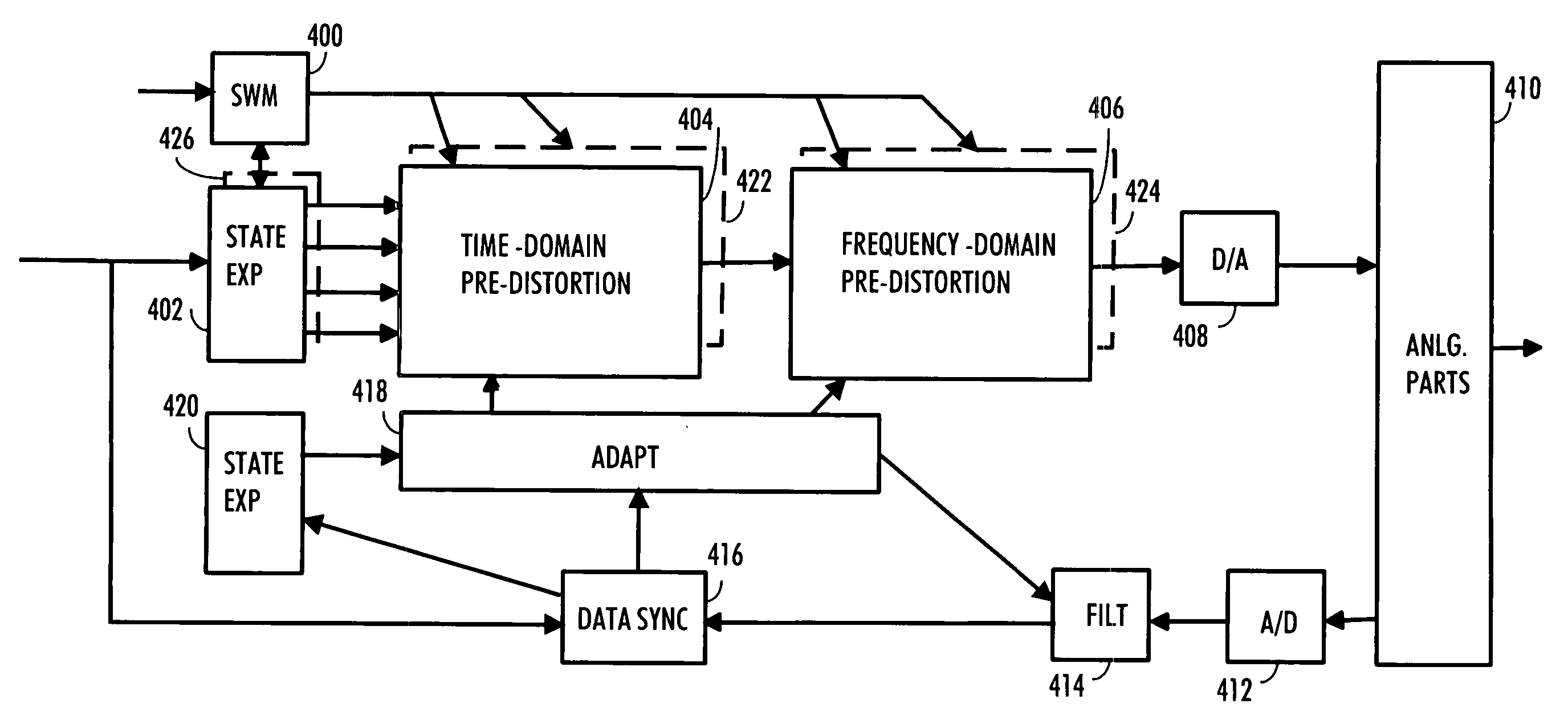
Embodiment Construction

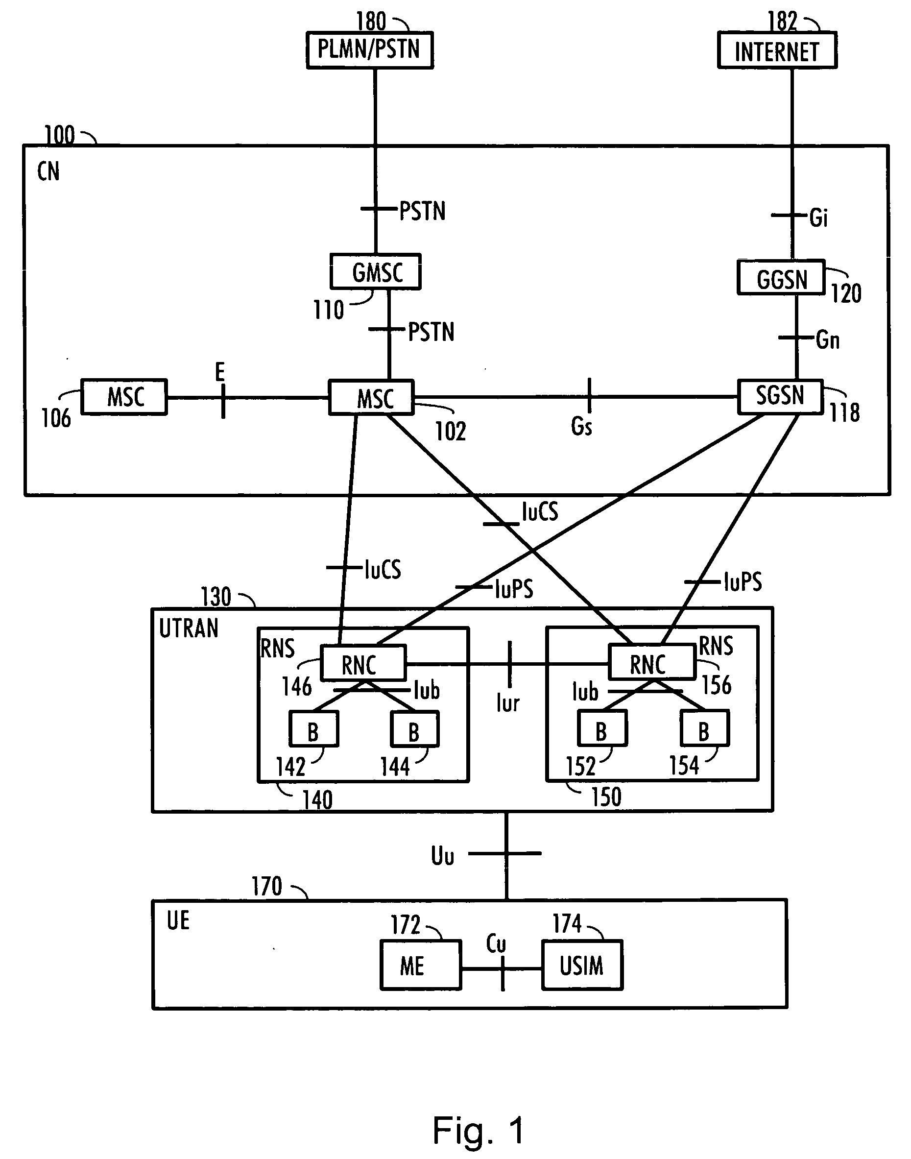
[0027] With reference to FIG. 1, an example of a data transmission system in which the preferred embodiments of the invention can be applied is shown. In FIG. 1, the embodiment is described in a simplified radio system, which represents, for example, a Code Division Multiple Access, (CDMA), system. The Code Division Multiple Access technique is used nowadays for example in radio systems which are known at least by the names IMT-2000 (International Mobile Telecommunications 2000) and UMTS (Universal Mobile Telecommunications System). The embodiments are not, however, restricted to these systems given as examples but a person skilled in the art may apply the solution to other radio systems provided with the necessary properties.

[0028]FIG. 1 is a simplified block diagram, which describes the most important network elements of the radio system and the interfaces between them. The structure and function of the network elements are not described in detail because they are generally known...


PUM


Abstract

A transmitter compensates for the non-linearities within a transmission chain. The transmitter includes, for instance, a first forming device for forming, on the basis of at least one set of signal properties, at least one state expansion vector comprising quantities characterizing a signal. The transmitter includes a modifier for modifying the signal characterizing quantities of at least one state expansion vector with the at least one time-domain compensation parameter vector and with the at least one frequency-domain compensation parameter vector to form a pre-distorted signal. The transmitter includes a second forming device for forming a feedback signal from an output signal of a transmission chain. The transmitter includes an adapter for adapting at least one time-domain compensation parameter vector for adapting at least one frequency-domain compensation parameter vector based on a residual error between a transmit signal and the feedback signal.

Description

[0001] This is a Continuation Application of U.S. patent application Ser. No. 10 / 630,975, filed Jul. 31, 2003, which claims the priority of U.S. Provisional Application No. 60 / 449,848, filed Feb. 27, 2003. The disclosures of the prior applications are hereby incorporated by reference in their entirety.BACKGROUND OF THE INVENTION [0002] 1. Field of the Invention [0003] The invention relates to a data transmission method, a base station and a transmitter in a telecommunication system. [0004] 2. Description of the Related Art [0005] Power amplifiers are required in radio telecommunication systems to amplify signals before transmitting the signal, because a radio signal attenuates on the radio path. Unfortunately, high-power radio-frequency amplifiers tend to be non-linear devices and therefore they in many cases cause distortion. This distortion is expressed, for example, as Inter-Symbol-Interference or out-off-band power in adjacent frequency bands. ACLR (Adjacent Carrier Leakage Rati...

Claims


Application Information

Patent Timeline
Patent Type & Authority Applications(United States)
IPC IPC(8): H04B1/04H04B1/707H04J13/00
CPCH03F1/3247H04B1/0475
Inventor KARJALAINEN, MIIASAARINEN, SAMUHEINIKOSKI, KAUKOTOLONEN, TEEMUYLINEN, JUHASUONPERA, JANILEHTINEN, RISTO
Owner NOKIA SOLUTIONS & NETWORKS OY
Why Eureka
Try Eureka