L1/L2 GPS receiver

a global positioning system and receiver technology, applied in the field of radio frequency receivers, can solve problems such as degrading the noise figure of the receiver, and achieve the effects of reducing power consumption, optimizing integration and performance, and reducing power dissipation

Inactive Publication Date: 2006-06-29
CSR TECH INC
View PDF14 Cites 26 Cited by
  • Summary
  • Abstract
  • Description
  • Claims
  • Application Information

AI Technical Summary

Benefits of technology

[0013] More particularly, the present invention includes a sub-harmonic frequency generator, which may include a sub-harmonic VCO, with different harmonics of the sub-harmonic frequency VCO providing the local oscillator signals for the L1 and L2 carriers. Downconversion in the sub-harmonic frequency generator or a first mixer then produces two intermediate frequencies (IF) for the L1 and L2 carriers. The VCO frequency and harmonic orders may be chosen such that the difference between these two IF signals is twice the desired final IF. The final IF may be obtained through a second mix in a second mixer with an LO signal that is halfway between the L1 and L2 IF frequencies. Since these IF signals generated in the first mixer are on either side of the LO frequency they can be separated by having the second mixer be an image reject mixer. The image reject mixer can be used to receive L1 and L2 simultaneously using both its outputs, or to switch between L1 and L2. The selection is accomplished by interchanging the ‘T’ and “Q” LO input signals of the second IR mixer. Since this switching is done at a lower IF frequency it does not cause unlocking of the phase locked loop (PLL) or the receiver tracking loop.
[0014] This receiver architecture is chosen to minimize power dissipation, while optimizing integration and performance. Operation of an on-chip integrated VCO at a frequency three to four times lower than the L1 / L2 RF carriers saves power in the VCO and PLL. Switching at the IF frequency consumes less power compared to RF or LO switching, and does not degrade the receiver noise figure. RF switches introduce front-end loss which degrades the receiver noise figure. Only one external split band filter is required at the front end to reject the first image frequencies for the L1 and L2 downconversion. The second image is rejected by the image reject function of the second mixer. There is no 3 dB degradation for simultaneous L1 / L2 herein.
[0015] A single fixed frequency VCO eliminates the need of LO switching, and eliminates the need of RF switches, while still providing simultaneous L1 and L2 capability.

Problems solved by technology

RF switches introduce front-end loss which degrades the receiver noise figure.

Method used


Image

  • L1/L2 GPS receiver
  • L1/L2 GPS receiver

Examples


Embodiment Construction

[0019] The present invention is directed to an improved system and method for simultaneously receiving or switching dual frequency carrier signals. The improved system and method provides efficient and effective simultaneous receiving or switching, without radio frequency switches or local oscillator switching. The preferred embodiments of the improved system and method are illustrated and described herein by way of example only and not by way of limitation.

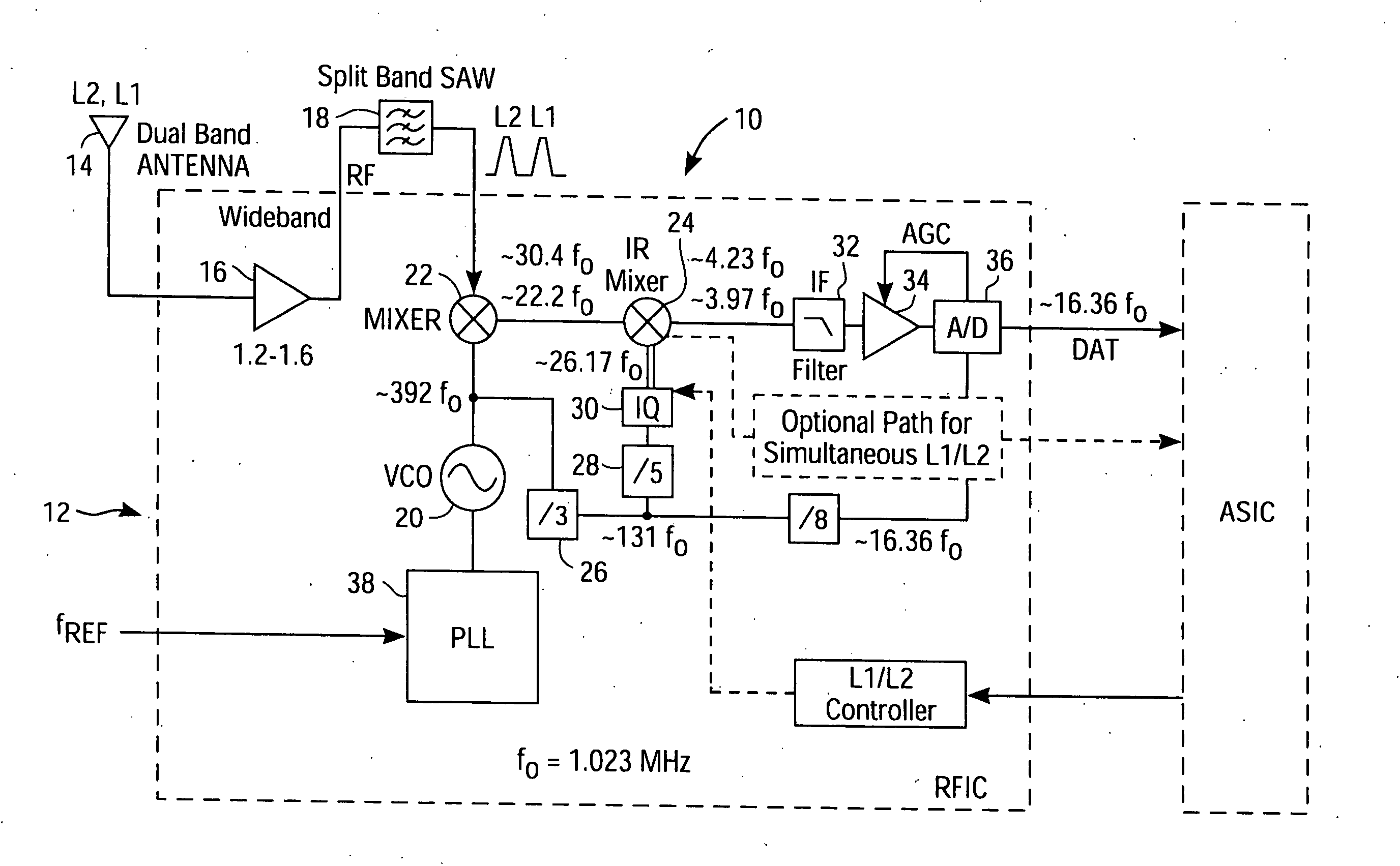
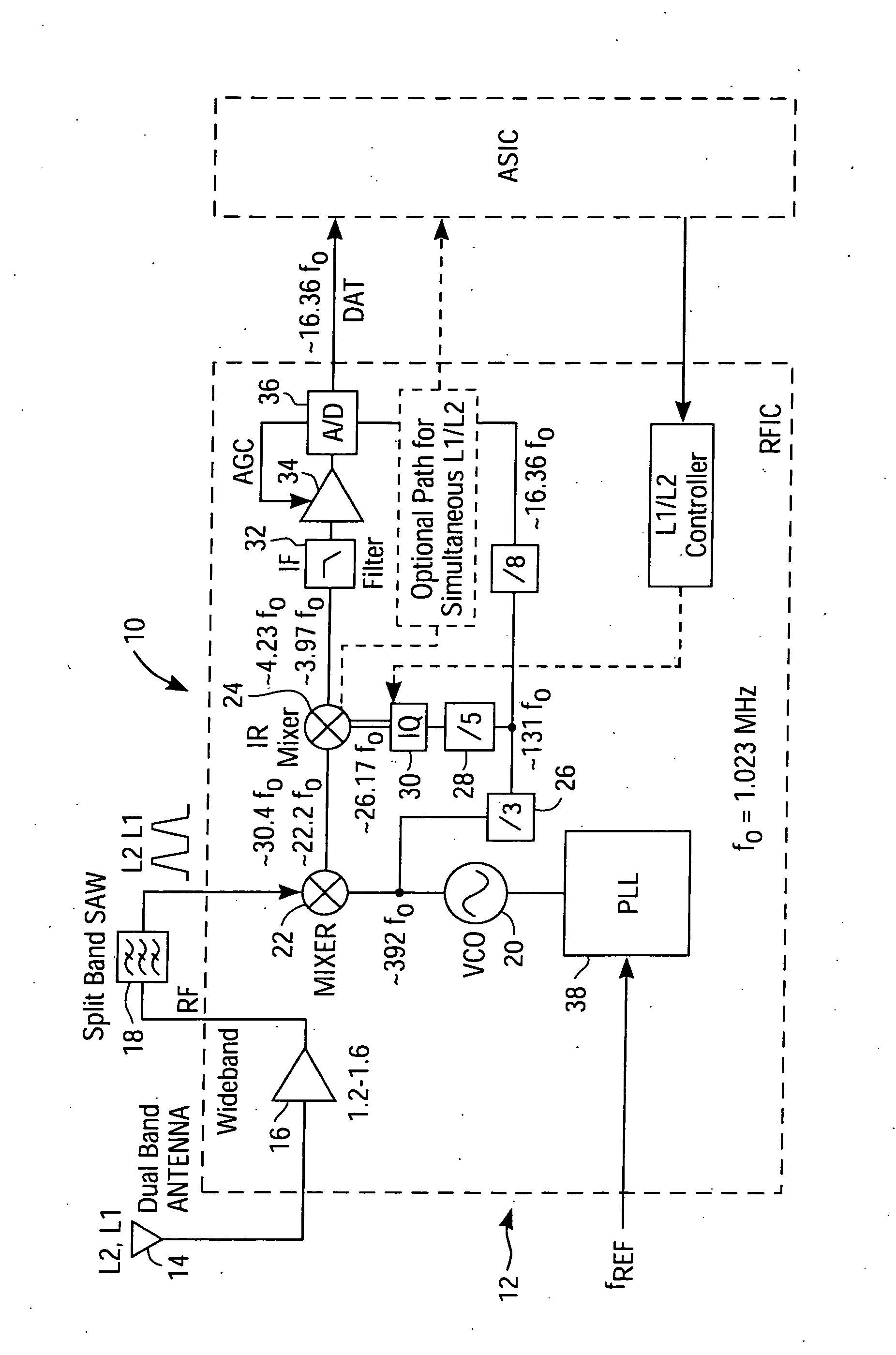
[0020] Referring now to the FIGURE, which illustrates a system 10 for simultaneously receiving or switching between dual frequency carrier signals, comprising a receiver 12 which is preferably a GPS receiver for the L1 and L2 carriers. The front-end of the receiver 12 consists of a dual band antenna 14 for receiving the dual frequency carrier signals, and a wide band low noise amplifier (LNA) 16, with 1.2 GHz to 1.6 GHz bandwidth, for amplifying the L1 and L2 carriers. A split band surface acoustic wave (SAW) filter 18 is then u...


PUM


Abstract

In a system and method for simultaneously receiving or switching between dual frequency carrier signals in a GPS receiver, the GPS receiver is adapted to utilize different harmonics of a sub-harmonic frequency generator, which may include a lower frequency voltage controlled oscillator (VCO) to detect the L1 and L2 GPS carriers. A sub-harmonic mixer may be used to simultaneously down convert the L1 and L2 signals to a lower intermediate frequency (IF). A second mixer may be an image reject (IR) mixer used to separate the downconverted L1 and L2 signals. This mixer may be configured to simultaneously monitor the L1 and L2 signals, or to switch between the L1 and L2 signals. High frequency switching is not required of the radio frequency (RF) input or local oscillator signals, and simultaneous L1 and L2 reception is enabled without and 3 dB image noise degradation. This system and method minimizes the RF components and power dissipation in a dual frequency GPS receiver, while optimizing the functionality and performance.

Description

BACKGROUND OF THE INVENTION [0001] 1. Field of the Invention [0002] The invention relates generally to radio frequency receivers, and more specifically to multiple band global positioning system (GPS) receivers used for navigation. [0003] 2. Description of the Related Art [0004] GPS satellites transmit data at two radio frequency (RF) system carrier frequencies: 1575.42 MHz (L1) and 1227.6 MHz (L2). GPS data from both carriers can be used to increase the position accuracy, and to provide carrier selectivity in case of interference or jamming of one of the carriers. [0005] A GPS receiver designed to receive the L1 and / or L2 carriers requires a method for receiving both signals simultaneously or efficiently switching between the signals. One solution is to duplicate all receiver parts and functions for the L1 and L2 bands. However, for low-power portable receivers, it is desirable to integrate the L1 and L2 functions as much as possible, to minimize the number of RF functions and powe...

Claims


Application Information

Patent Timeline
Patent Type & Authority Applications(United States)
IPC IPC(8): H04B1/18H04B1/10G01S19/29G01S1/00G01S19/32H04B1/40
CPCG01S19/32G01S19/34H04B1/005H04B1/28H04B1/406
Inventor DUBASH, NOSHIR B.TSO, ROBERT
Owner CSR TECH INC
Why Eureka
Try Eureka