Intravenous pacemaker electrode

a pacemaker electrode and electrode electrode technology, applied in the field of intravenous pacemaker electrodes, can solve the problems of increasing power consumption, reducing the service life of the pacemaker battery, and the pacemaker no longer performing the intended function, and achieve the effect of low changes over tim

Inactive Publication Date: 2006-06-29
SIEMENS AG
View PDF17 Cites 1 Cited by
  • Summary
  • Abstract
  • Description
  • Claims
  • Application Information

AI Technical Summary

Benefits of technology

[0006] The object of the invention is to specify an implantable pacemaker electrode, which is distinguished by long-term usability combined with particularly low changes over time.

Problems solved by technology

In the extreme case, such a change in the stimulation threshold results in the pacemaker no longer performing its intended function.
In cases in which the pacemaker continues to perform its function despite an increase in the stimulation threshold, power consumption increases and hence the service life of the pacemaker battery decreases.

Method used


Image

  • Intravenous pacemaker electrode
  • Intravenous pacemaker electrode
  • Intravenous pacemaker electrode

Examples


Embodiment Construction

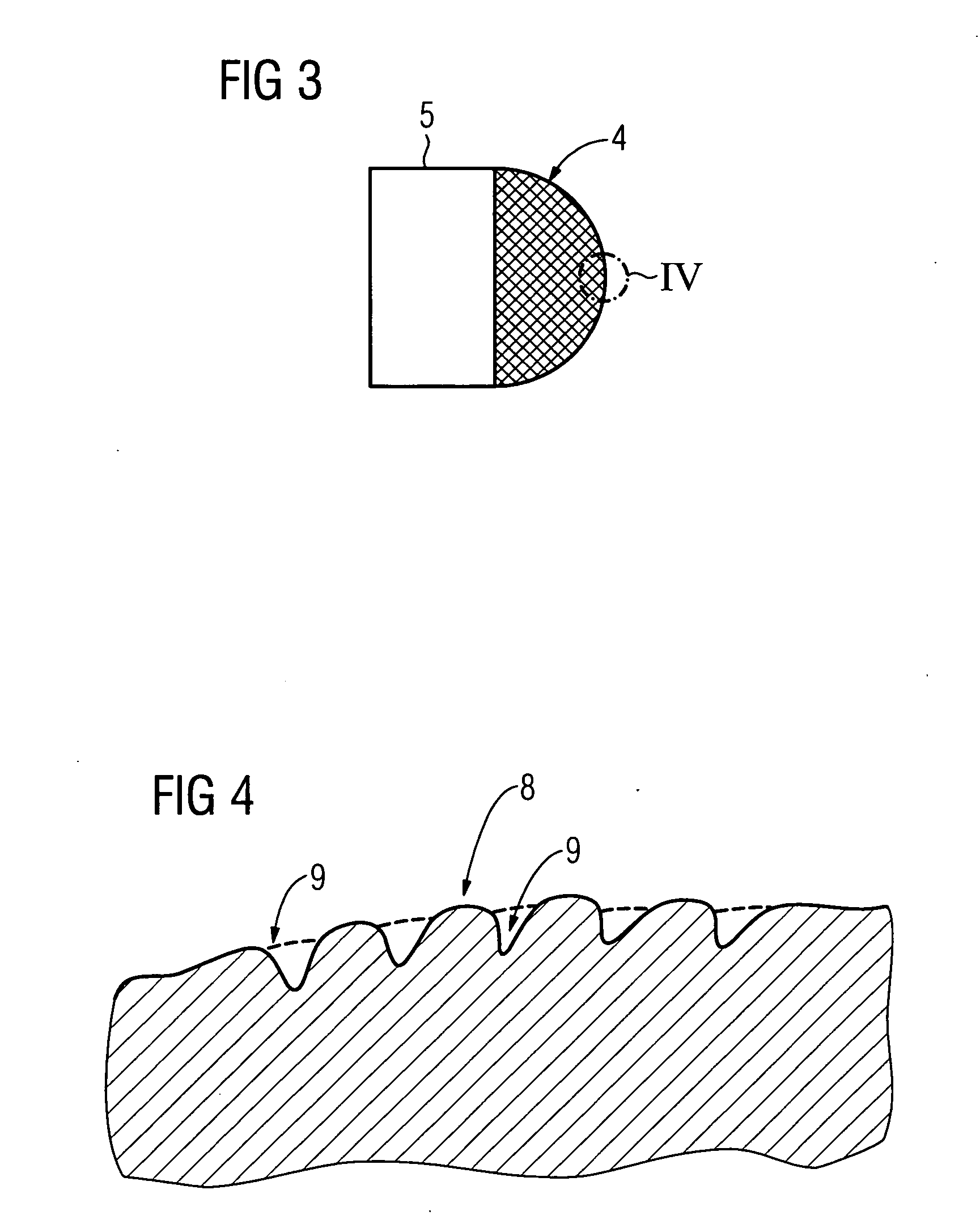
[0043] Corresponding parts, or parts with the same function, are given the same references in all figures.

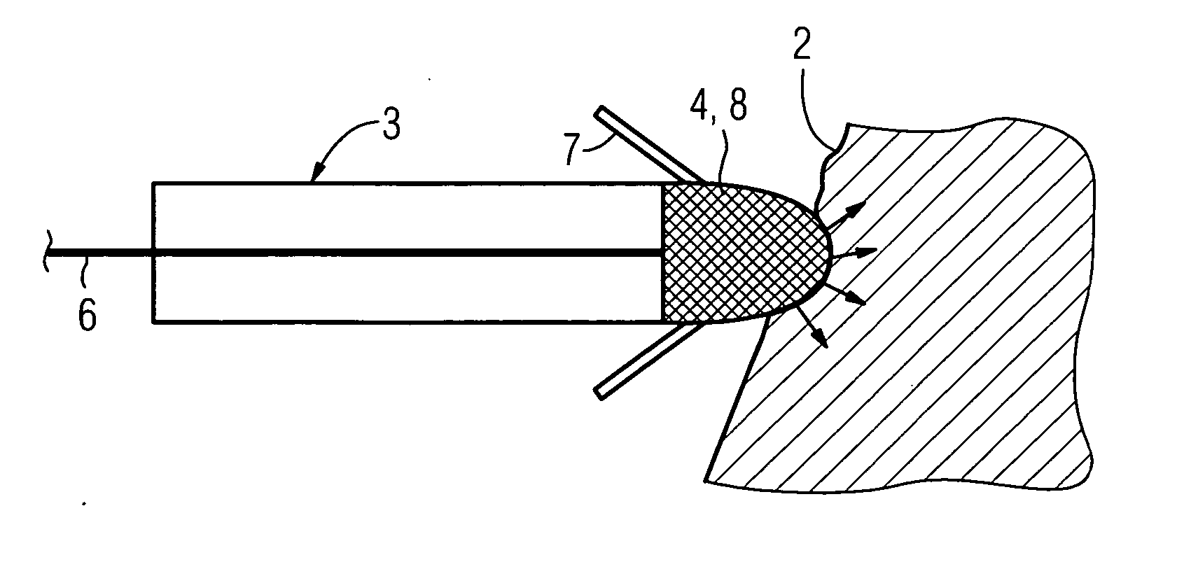
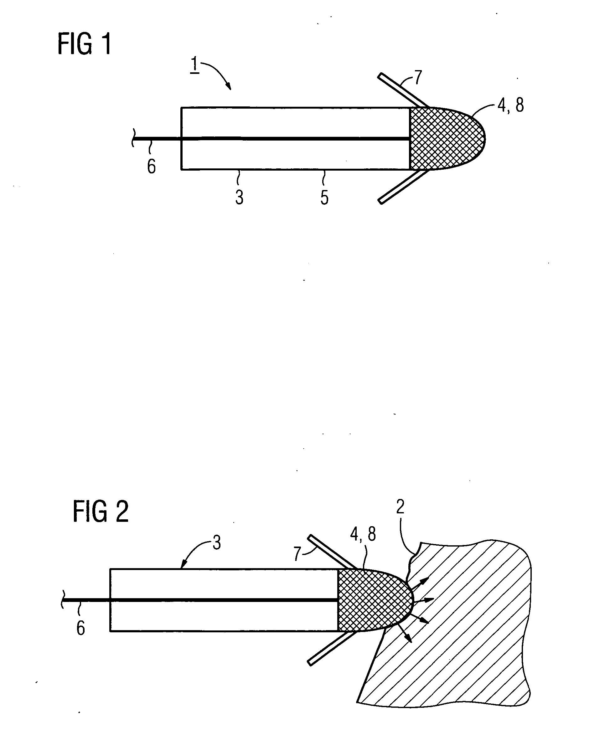
[0044]FIGS. 1 and 2 show schematically part of a pacemaker electrode 1 for transmitting stimulation pulses to a myocardium 2. The pacemaker electrode may be from a unipolar pacemaker or equally from a bipolar pacemaker, where in each case it is possible not only to transmit stimulation pulses to the myocardium, but also to detect, or sense, signals coming from the heart. An electrode tip 4 is attached to the distal end of an electrode cable 3 of the pacemaker electrode 1. An electrical conductor 6 runs inside the electrode cable 3, which has an insulating sleeve 5, up to the electrode tip 4. Two fold-out anchoring flaps 7 are attached to this tip, which act like an expandable anchor to enable or facilitate the anchoring of the electrode tip 4 in the tissue of the patient. The anchoring aids 7 may also differ from the simplified diagram, for example they may have a form known fr...


PUM


Abstract

An intravenous pacemaker electrode has an electrode tip designed to release a drug, where the drug contains at least one of the active substances sirolimus, paclitaxel, everolimus, fibrin, rapamycin, and tacrolimus.

Description

CROSS REFERENCE TO RELATED APPLICATION [0001] This application claims priority of the German application No. 10 2004 062 394.5 DE filed Dec. 23, 2004, which is incorporated by reference herein in its entirety. FIELD OF THE INVENTION [0002] The invention relates to an intravenous pacemaker electrode that enables the release of a drug, and a method suitable for manufacturing such a pacemaker electrode. BACKGROUND OF THE INVENTION [0003] A pacemaker electrode intended for releasing a drug is known for example from U.S. Pat. No. 4,922,926. [0004] Implantable pacemaker electrodes have an electrode tip, which must be fixed permanently to the myocardium. In addition to the mechanical anchoring of the electrode tip to the heart muscle, it should be ensured that electrical stimulation pulses can be transmitted under as constant conditions as possible. For this purpose, an electrode device for intracorporal stimulation of the body tissue, known from European patent EP 0 620 024 B1, for exampl...

Claims


Application Information

Patent Timeline
Patent Type & Authority Applications(United States)
IPC IPC(8): A61N1/05
CPCA61N1/0568
Inventor MASCHKE, MICHAEL
Owner SIEMENS AG
Why Eureka
Try Eureka