FBGA and COB package structure for image sensor

a technology of image sensor and package structure, applied in the direction of semiconductor/solid-state device details, electrical equipment, semiconductor devices, etc., can solve the problems of reducing the yield rate during the packaging process, damage to sensitive chips, and affecting the quality of the devi

Active Publication Date: 2006-07-06
ADVANCED CHIP ENG TECH
View PDF9 Cites 26 Cited by
  • Summary
  • Abstract
  • Description
  • Claims
  • Application Information

AI Technical Summary

Benefits of technology

[0009] Therefore, the main objective of the present invention is to provide a package for image sensor, such as COB (Chip On Board) or

Problems solved by technology

Due to the manufacturing technology and material requirements, packages having built-up layers often include a number of degassing holes in the metal layers.
If the unwanted particles are not removed from the sensor, it leads to downgrade the quality of the device.
In order to achieve the purpose, the removal by manual may damage the sensitive chip.
One drawback of the COB is lower yield rate during packaging process due to particle contaminatio

Method used


Image

  • FBGA and COB package structure for image sensor
  • FBGA and COB package structure for image sensor
  • FBGA and COB package structure for image sensor

Examples


Embodiment Construction

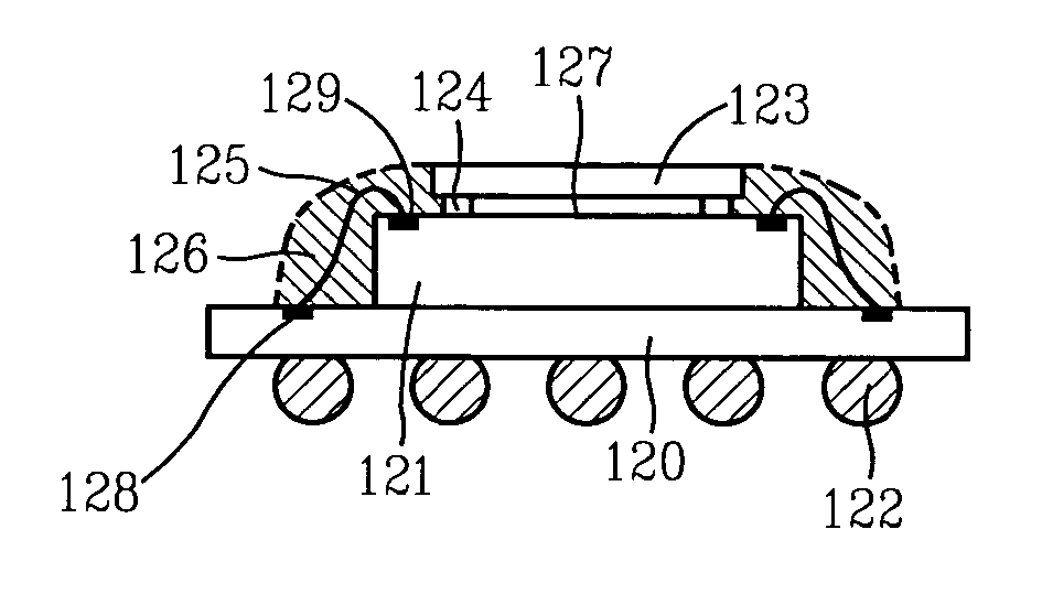
[0025] Some sample embodiments of the invention will now be described in greater detail. Nevertheless, it should be recognized that the present invention can be practiced in a wide range of other embodiments besides those explicitly described, and the scope of the present invention is expressly not limited except as specified in the accompanying claims. Then, the components of the different elements are not shown to scale. Some dimensions of the related components are exaggerated and meaningless portions are not drawn to provide clearer description and comprehension of the present invention. The structure is adaptable to the FBGA (Fine-pitch Ball Grid Array) and COB (Chip On Board) type package. The present invention benefits lower cost and more simple process than the die scale package (CSP). The CSP type package suffers higher cost issue. Further, data processing speed of the FBGA package is far faster than conventional TSOP (Thin Small Outline Package) for inter-connection wires ...


PUM


Abstract

A structure of package comprises a die placed on printed circuit board. A glass substrate is adhered on an adhesive film pattern to form an air gap area between the glass substrate and the chip. Micro lens are disposed on the chip. A lens holder is fixed on printed circuit board. The glass substrate can prevent the micro lens from particle contamination.

Description

BACKGROUND OF THE INVENTION [0001] 1. Field of the Invention [0002] This invention relates to a package structure, and more particularly to an image sensor package structure that can prevent the micro lens from particle contamination. [0003] 2. Description of the Prior Art [0004] The package can have a core made of a common material such as glass epoxy, and can have additional layers laminated onto the core. These additional layers are also known as “built-up” layers. The built-up layers are typically formed from alternating layers of dielectric material and conductive material. Patterns may be built in the metal or conductive layer through various etching processes such as wet etching which are known in the art and will not be described further herein. Plated through holes called vias are used to make interconnects between various layers of metal. Using these layers and vias, several layers of interconnections may be built up. [0005] Input / Output functions are typically accomplishe...

Claims


Application Information

Patent Timeline
IPC IPC(8): H01L23/02
CPCH01L27/14618H01L27/14625H01L27/14627H01L2224/48227H01L2924/10253H01L2924/3011H01L2924/00H01L2924/16235H01L2924/181H01L2924/00012H01L27/14
Inventor YANG, WEN-KUNYANG, CHIN-CHENSUN, WEN-BINCHANG, JUI-HSIENYU, CHUN HUIYUAN, HIS-YING
Owner ADVANCED CHIP ENG TECH
Why Eureka
Try Eureka