Assembling structure of field coil

a field coil and assembly technology, applied in the direction of magnetically actuated clutches, mechanical actuators, mechanical apparatus, etc., can solve the problems of poor influence, high manufacturing cost, peripheral electronic parts, etc., and achieve the effect of improving mounting efficiency, simple structure and reducing manufacturing cos

Active Publication Date: 2006-07-06
HANON SYST
View PDF7 Cites 7 Cited by
  • Summary
  • Abstract
  • Description
  • Claims
  • Application Information

AI Technical Summary

Benefits of technology

[0015] Accordingly, the present invention is directed to an assembling structure of field coil that substantially obviates one or more problems due to limitations and disadvantages of the related art. An object of the present invention is to provide an assembling structure of field coil, which has a simple structure for mounting a diode or a diode and a resistor to a field coil assembly, thereby improving a mounting efficiency, reducing a manufacturing cost by reducing the number of parts and manufacturing processes, and automatically manufacturing the field coil assembly.

Problems solved by technology

When surge voltage and counter electromotive force are generated, it may have a bad influence, such as occurrence of short, on the peripheral electronic parts.
Therefore, the conventional field coil assembly 10 has several problems in that a manufacturing cost is expensive due to lots of parts, and in that it is impossible to automatically manufacture the field coil assembly due to complicated manufacturing processes when only the diode 21 is mounted or the diode 21 and the resistor 22 are mounted.

Method used


Image

  • Assembling structure of field coil
  • Assembling structure of field coil
  • Assembling structure of field coil

Examples


Embodiment Construction

[0030] Reference will now be made in detail to the preferred embodiments of the present invention, examples of which are illustrated in the accompanying drawings.

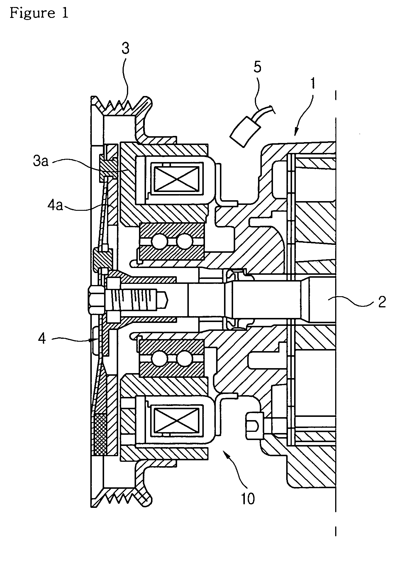
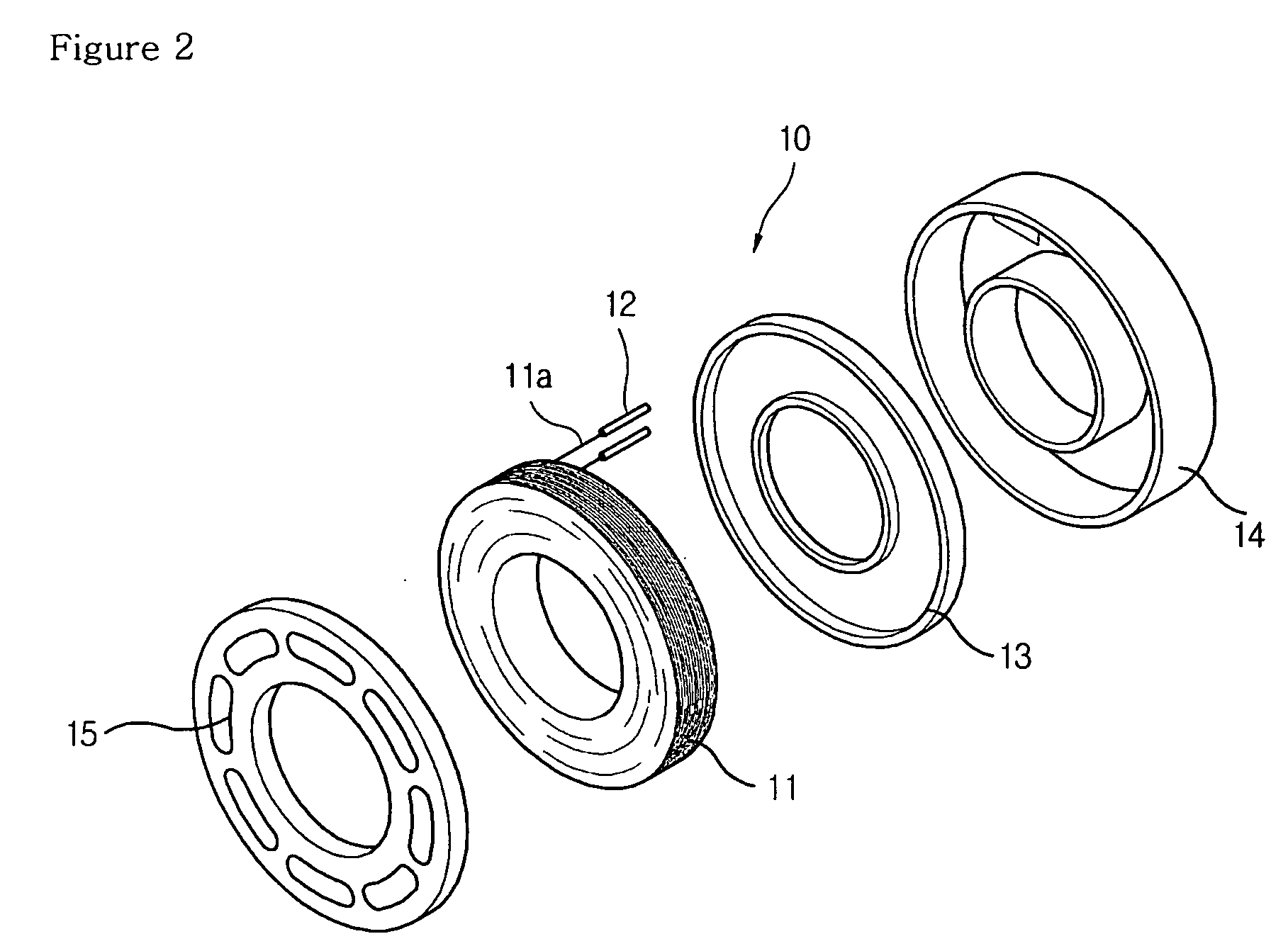
[0031] Description of the same parts and functions as the prior arts will be omitted.

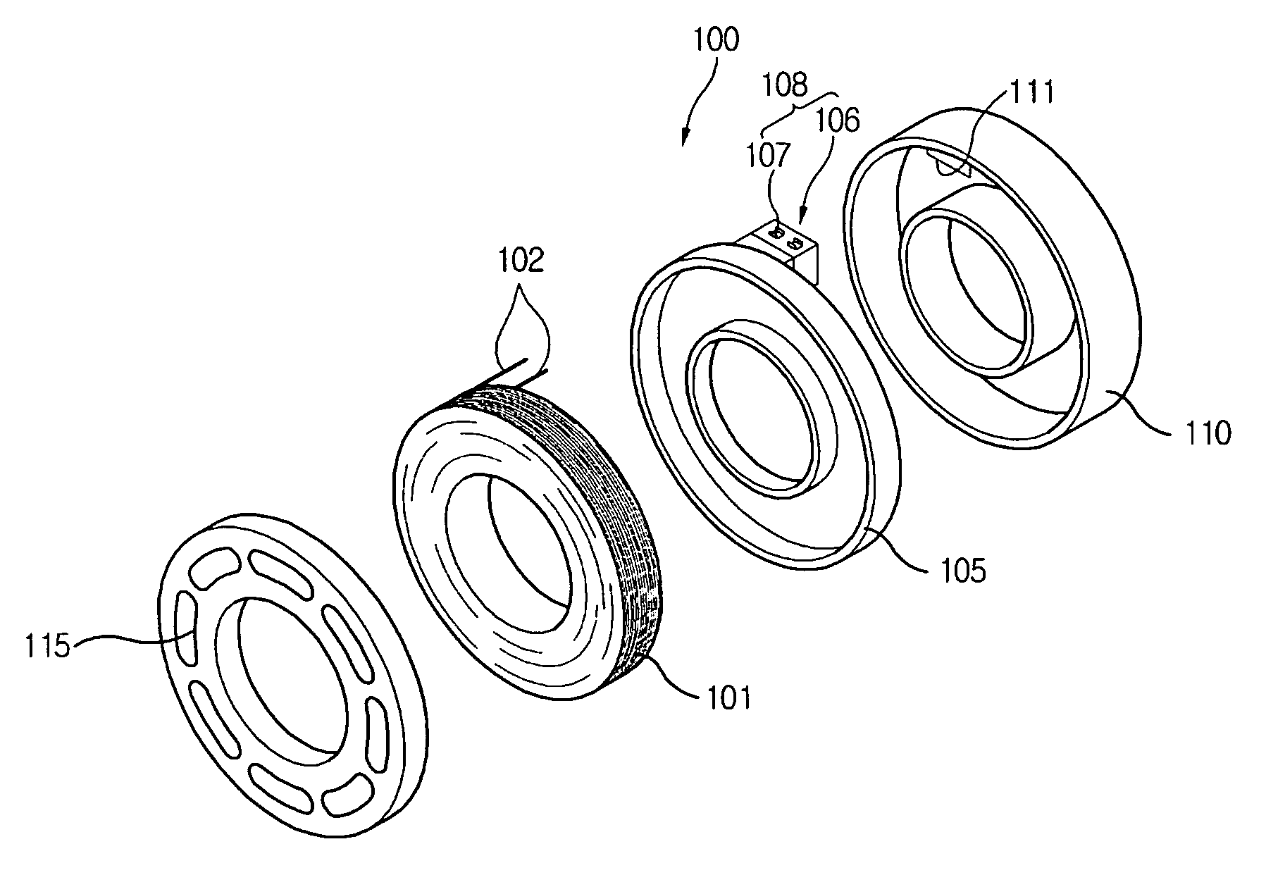
[0032]FIG. 5 is an exploded perspective view of a field coil assembly according to a first preferred embodiment of the present invention, FIG. 6 is a perspective view of a sleeve in which the field coil assembly of the first preferred embodiment, a diode and a resistor are embedded, FIG. 7 is a perspective view showing a connection relation between terminals and the diode before the sleeve of the first preferred embodiment is injection-molded, FIG. 8 is a perspective view showing a connection relation among the terminals, the diode, and the resistor before the sleeve of the first preferred embodiment is injection-molded, and FIG. 9 is a plan view showing a state before a protector is formed after the diode and the resistor are seated on s...


PUM

PropertyMeasurementUnit
structureaaaaaaaaaa
assembling structureaaaaaaaaaa
electromagnetic fieldaaaaaaaaaa

Abstract

The present invention relates to an assembling structure of field coil, which has a simple mounting structure for a diode and a resistor to cut an off-noise of an electromagnetic clutch and to prevent damage of peripheral parts due to surge voltage generation when power source applied to an electronic coil body is cut off, thereby improving a mounting efficiency, reducing a manufacturing cost by reduction of the number of parts, and realizing an automatic production. The assembling structure of field coil includes an electronic coil body(101), a core ring(110) and a sleeve(120) having a first and second terminals(131)(132), and a case that has a receiving part (135) and a first and second connection parts(136)(137).

Description

TECHNICAL FIELD [0001] The present invention relates to an assembling structure of field coil, and more particularly, to an assembling structure of field coil, which has a simple mounting structure for a diode and a resistor to cut an off-noise of an electromagnetic clutch and to prevent damage of peripheral parts due to surge voltage generation when power source applied to an electronic coil body is cut off, thereby improving a mounting efficiency, reducing a manufacturing cost by reduction of the number of parts, and realizing an automatic production. BACKGROUND ART [0002] In general, a field coil assembly of an electromagnetic clutch is an electric device for transmitting driving force of a pulley rotating by an engine to a hub disc of a compressor driving shaft in such a manner that an electromagnetic field is formed by electromagnetic induction of a wound coil when power source is supplied, and the hub disc of the compressor driving shaft is attracted to the friction surface of...

Claims


Application Information

Patent Timeline
Patent Type & Authority Applications(United States)
IPC IPC(8): H01F27/29F16D27/112F16D27/10F16D27/14H01F7/06H01F7/20H01F27/02H01F27/04H01F27/40
CPCF16D27/112F16D27/14F16D2027/001H01F7/06H01F7/20H01F27/022H01F27/04H01F27/40H01F2007/062F16D27/10
Inventor CHUNG, SUKJAE
Owner HANON SYST
Why Eureka
Try Eureka