Device for multifocal confocal microscopic determination of spatial distribution and for multifocal fluctuation analysis of fluorescent molecules and structures with flexible spectral detection

a technology of multi-focal confocal and spatial distribution, which is applied in the field of multifocal confocal microscopic determination of spatial distribution and multi-focal fluctuation analysis of fluorescent molecules and structures with flexible spectral detection, can solve the problems of difficult or impossible comparison of different measurement points with each other, difficult or impossible to define well-defined positioning of different successive measurement points within the sample, and the use, in particular, of the results of fcs analysis (as

Inactive Publication Date: 2006-07-06
LEICA MICROSYSTEMS CMS GMBH
View PDF7 Cites 28 Cited by
  • Summary
  • Abstract
  • Description
  • Claims
  • Application Information

AI Technical Summary

Benefits of technology

[0005] The invention relates to a device for simultaneously illuminating several points on the sample (e.g., along a line) and for simultaneously recording and processing in parallel the fluorescent signal from these points. Processing comprises autocorrelation analysis of one and / or cross-correlation analysis of several spectral detection channels, analysis of the intensity distribution histogram in various channels, and similar methods, hereinafter referred to as FCS measurement. In particular, detection of the fluorescent signal can occur with the help of a spectrometer that enables flexible and freely selectable splitting of the fluorescence into several channels. Different groups of points on the sample may be scanned with the help of a beam scanner for moving the excitation points over the sample or with a sample scanner for moving the sample over the excitation points in order to record the spatial distribution of the fluorescence, and to determine the dynamic spatial resolution characteristics.

Problems solved by technology

The inherent, relatively long duration of an FCS measurement of at least a few seconds makes it very difficult to compare different measurement points with each other because living cells are analyzed in typical applications so that movements and structural changes occur within seconds and even faster and as a result well-defined positioning for different successive measurement points within the sample is difficult or impossible.
The use, in particular, of the results of FCS analysis (as described above) as a contrast-providing signal for imaging in 1, 2, or 3 dimensions is thus made difficult or impossible.
Avalanche photo diodes (APDs) that possess a very small detector surface are primarily used, for which reason they are not suitable for spectral detection for which purpose they have been used to date (Leica, Zeiss).

Method used


Image

  • Device for multifocal confocal microscopic determination of spatial distribution and for multifocal fluctuation analysis of fluorescent molecules and structures with flexible spectral detection
  • Device for multifocal confocal microscopic determination of spatial distribution and for multifocal fluctuation analysis of fluorescent molecules and structures with flexible spectral detection
  • Device for multifocal confocal microscopic determination of spatial distribution and for multifocal fluctuation analysis of fluorescent molecules and structures with flexible spectral detection

Examples


Embodiment Construction

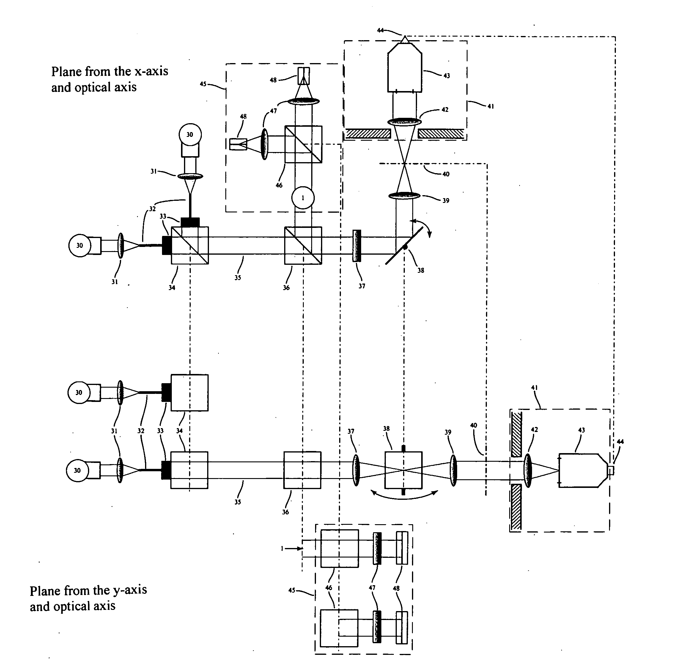
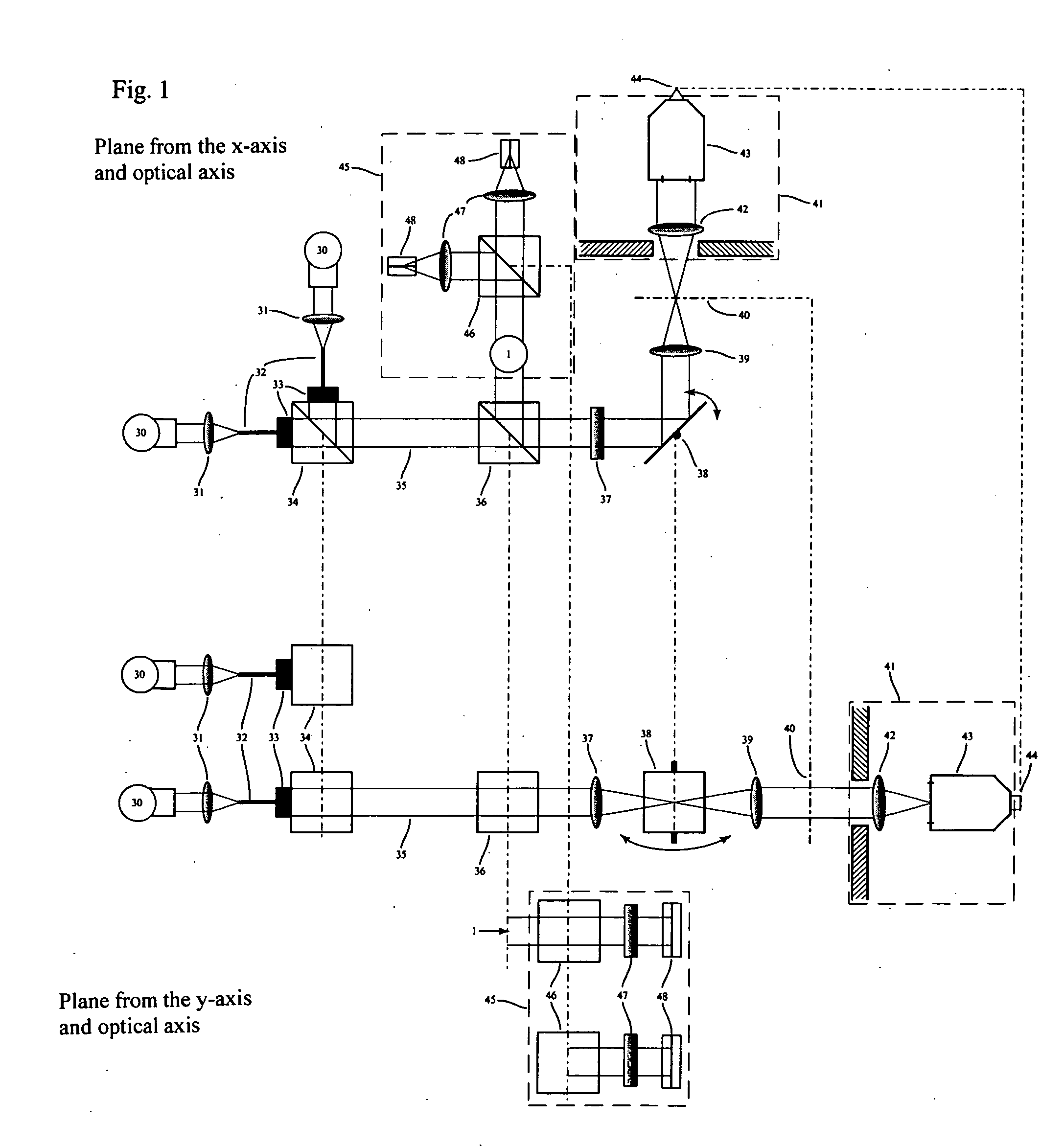
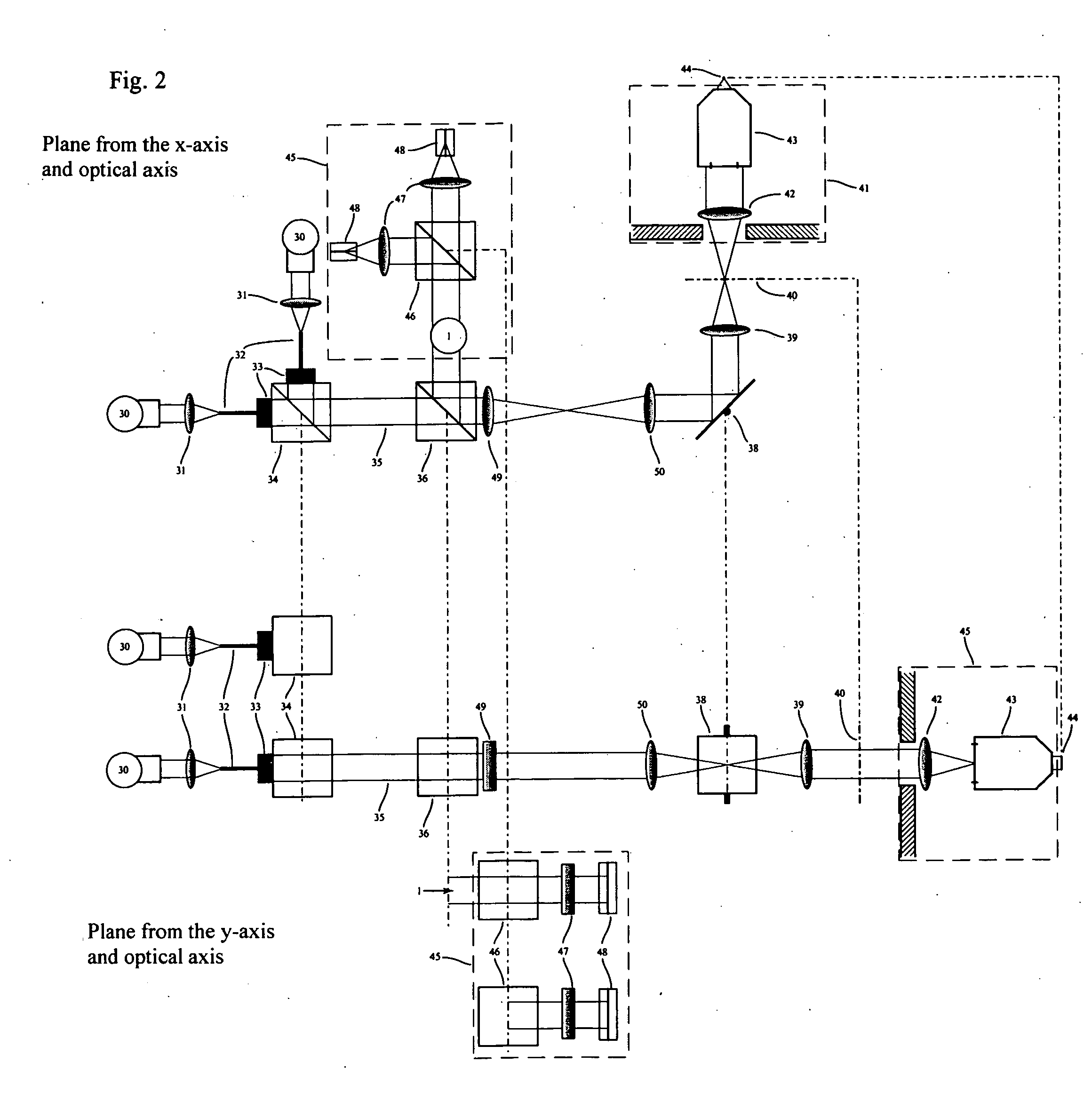
[0027]FIG. 1 shows a possible implementation of a line scanner as described, for example, in Pawley (1995) as a translation of the multifocal concept. Light from one or several lasers 30 are coupled in a fiber 32 via an optic 31 and collimated with the help of an output / collimation optic 33 and directed toward a beam combiner34. Combination of several lasers may also result from cascading. The collimated light 35 can be spread asymmetrically in x-direction and y-direction by an anamorphotic expander because it is focused on a point in x-direction and on a line in y-direction. The laser light is directed through a beam splitter 36 and a cylindrical lens 37 that is implemented such that it has no effect in x-direction, and in y-direction focuses the light onto the center of a rotatable mirror 38 that is perpendicular to the midline. This mirror may be rotated in a well-defined manner, e.g., with a galvanometric drive. At the same time, the center of the mirror is located in the focal ...


PUM


Abstract

Many points on a sample are tested simultaneously in parallel in an FCS method with multifocal illumination and / or detection.

Description

RELATED APPLICATIONS [0001] This application claims priority to German patent application number DE 10 2005 000 915.8 filed Jan. 6, 2005, which is incorporated herein by reference in its entirety. BACKGROUND OF THE INVENTION [0002] Systems known from the literature and from practice for combining fluorescence microscopy with FCS consist, for example, of a CLSM that is attached to an optical port of a microscope stand for the purpose of imaging, and of a separate illumination and detection unit for FCS that is attached to another port of the stand and serves to record and process the fluorescence signal at one point in each case (Zeiss). In a further implementation, fluorescence microscopy is effected via an epifluorescence setup and FCS measurement via a separate unit as just described (Brock, 1999). In a further implementation, imaging is effected using a CLSM, and the FCS excitation and detection unit via the same optic using the same (DKFZ) or separate detectors (Leica). [0003] I...

Claims


Application Information

Patent Timeline
Patent Type & Authority Applications(United States)
IPC IPC(8): G01J3/30
CPCG01J3/14G01J3/36G01N21/6458G02B21/0064G02B21/0072
Inventor WACHSMUTH, MALTERIPPE, KARSTENHEUVELMAN, GERRIT
Owner LEICA MICROSYSTEMS CMS GMBH
Why Eureka
Try Eureka