

Patterned conductive textile sensors and devices
- Summary
- Abstract
- Description
- Claims
- Application Information
AI Technical Summary
Benefits of technology
Problems solved by technology
Method used
Image

Examples
examples of invention
Patterned Textile Sensors
EXAMPLE 1
Directional Sensing Patterns
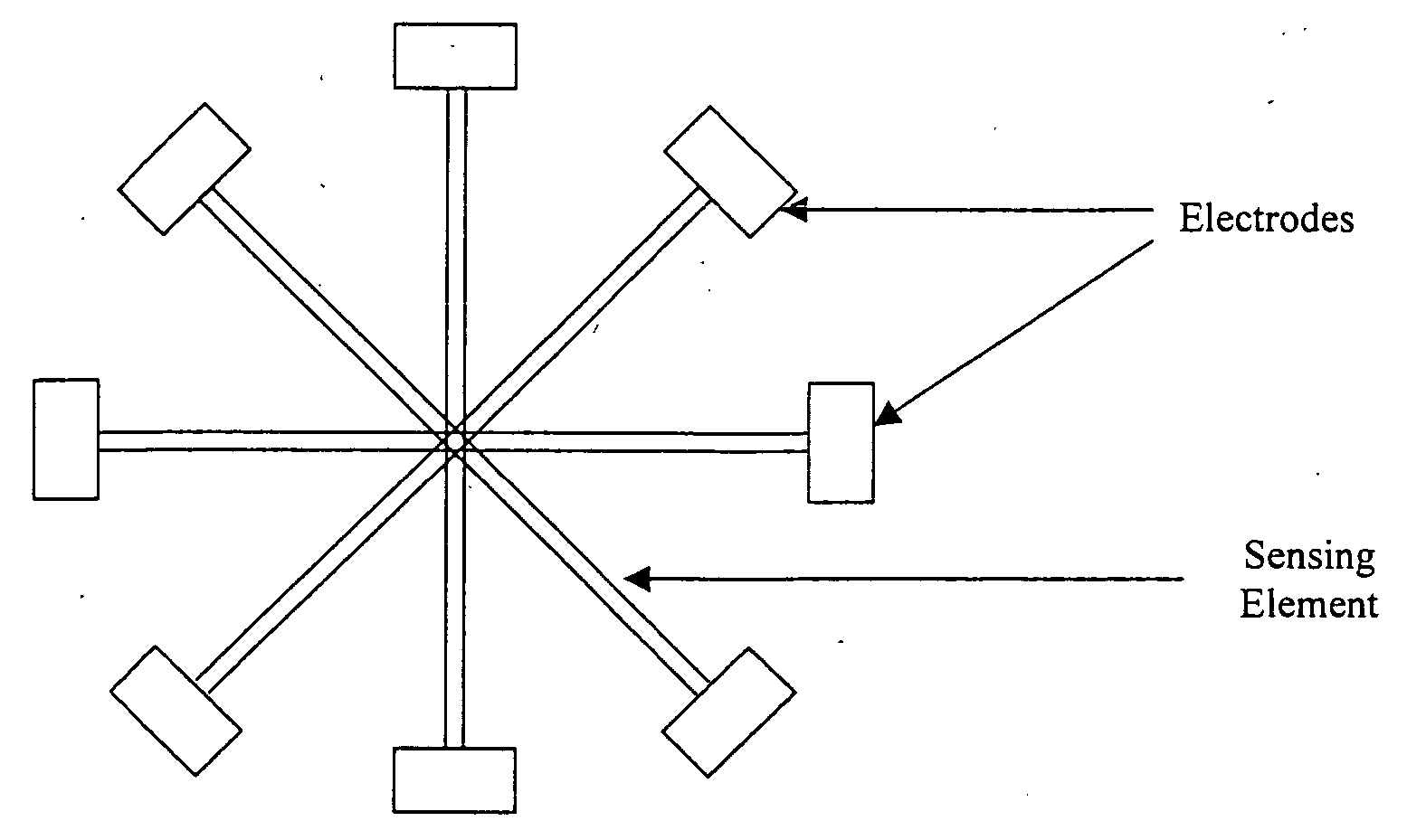
[0066]FIG. 1 shows a pattern incorporated on fabrics, woven, knitted or non-woven, braids, can be used for measuring strain in various directions, i.e. 0°, 90° and ±45°. The directions are selected after considering the particular textile structure used in terms of its anisotropic properties.
EXAMPLE 2
Shear Sensing Units
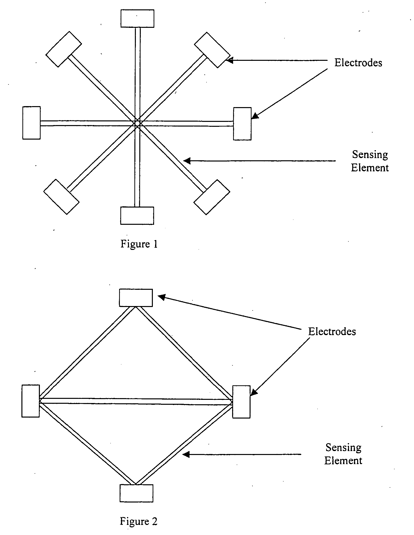
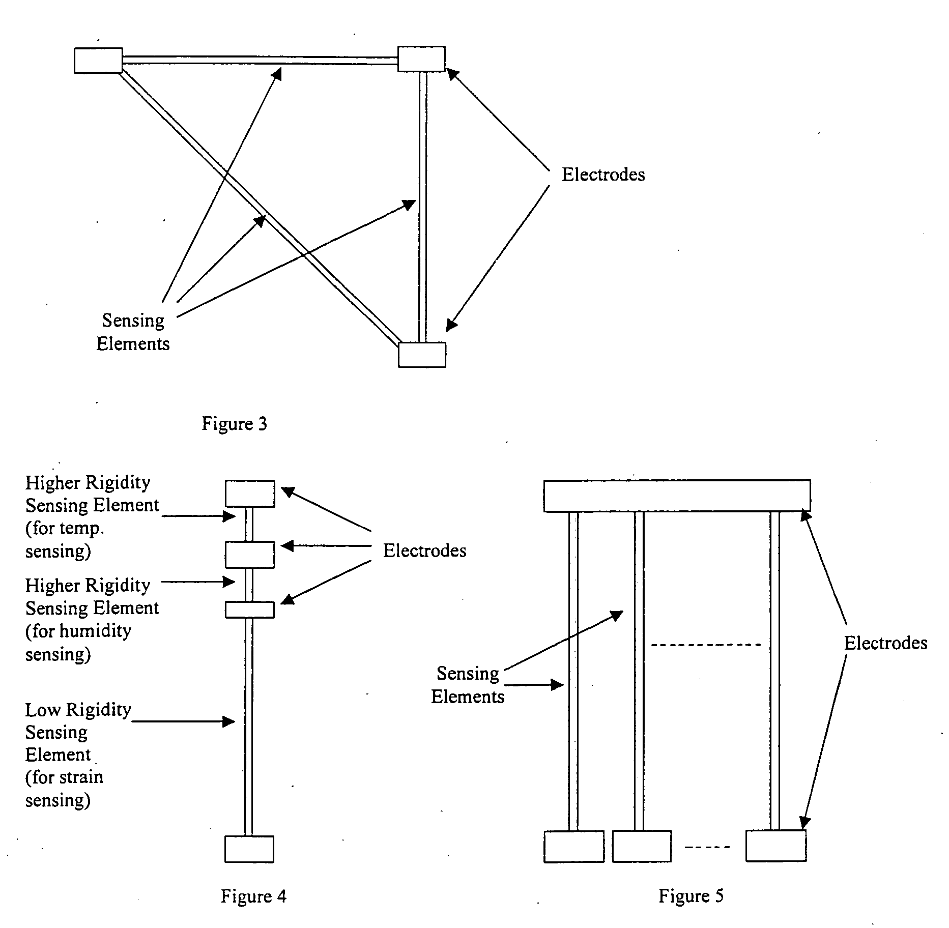
[0067] Patterns in FIG. 2 and FIG. 3 can be incorporated to measure the in-plane shear of the structures. The directions are selected after considering the particular textile structure used in terms of its anisotropic properties.
EXAMPLE 3
Simultaneous Measurement Unit for Temperature, Humidity and Strain
[0068]FIG. 4 shows a pattern that is printed on one-dimensional structures such as filament yarns, staple yarns, narrow fabrics such as two dimensional braids, tubular knits, woven fabrics etc. The conductive polymer is coated on the structure which has at least two parts, one has a modulus at least...
example 4
Vapor Deposition of Pyrrole Under the Electric-Field
[0083] The oxidizing agent is dissolved in an appropriate solvent and the liquid is applied by any of the above methods, jetted, screen-printed or padded onto the substrates.
[0084] After printing of oxidizing agent, pyrrole is coated on the substrate by vapor deposition while it is still wet, at an atmosphere saturated with pyrrole vapor under vacuum condition at room temperature and applying the electric-field. By alternating the direction of the electrical field in either side-way, vertical or inclined in different angles, strength of voltage applied (5KV to 30KV), the morphology and orientation of polymer chains will be changed correspondingly. A general schematic of this arrangement is shown in FIG. 9.
Stabilization of the PPy-Coated Fabric
[0085] Many researchers have studied different methods to improve the stability of the PPy-coated fabrics according to the following:
[0086] 1. By the use of different types of dopants
[0...
example 1
After-Washing of the PPy-Coated Fabrics in Various Conditions
[0090] Up to now, only the washing fastness of the PPy-coated fabric has been studied and it was found that the washing fastness of the PPy-coated fabric was satisfactory. However, the change of electrical-resistance of the PPy-coated fabric towards various washing conditions was still unknown. It is believed that various washing conditions (e.g. different washing temperature, different types of detergents and different duration) will impact different effect on the properties (electrical properties, gauge factor, morphology etc.) of the PPy-coated fabrics and the washing process will also impact a stabilizing effect of the PPy-coated fabric by accelerate the ageing of the coated PPy.
PUM
| Property | Measurement | Unit |
|---|---|---|
| Time | aaaaa | aaaaa |
| Temperature | aaaaa | aaaaa |
| Electrical conductivity | aaaaa | aaaaa |
Abstract
Description
Claims
Application Information