Apparatus and methods for tibial plateau leveling osteotomy

a technology of tibial plateau and osteotomy, which is applied in the field of bone fixation plates, can solve the problems of excessive wear of the cartilage of the joint, unstable dog's joint, and misplacement of the proximal screw or screw into the joint, and achieve the effect of promoting the fastening of the cut bone sections

Inactive Publication Date: 2006-07-06
CADMUS CALVIN M
View PDF17 Cites 48 Cited by
  • Summary
  • Abstract
  • Description
  • Claims
  • Application Information

AI Technical Summary

Benefits of technology

[0024] The present invention is directed to a new bone fixation plate to be used in an improved procedure for canine tibial plateau leveling osteotomy. The improved bone fixation plate promotes fastening of the cut bone sections resulting from an optimal centered osteotomy. With a centered osteot

Problems solved by technology

This damage leaves the dog's joint unstable and lameness and joint inflammation, i.e. arthritis, are common consequences.
This phenomenon, often referred to as tibial thrust, results in excessive wear of the cartilage of the joint.
Current art bone plates, however, have lead to several problems.
First, the large footprint and geometric configuration of the triangular proximal portion of the bone plate creates sub-optimal mounting configurations for the procedure.
This contouring combined with the close proximity to the interior of the femoro tibial joint 40 can cause the misplacement of the proximal screw or screws into the joint.
Thus, screws placed in the softer cancellous bone have a higher probability of loosening their purchase or stripping out.
In addition, cancellous bone screws generally have more prominent screw threa

Method used


Image

  • Apparatus and methods for tibial plateau leveling osteotomy
  • Apparatus and methods for tibial plateau leveling osteotomy
  • Apparatus and methods for tibial plateau leveling osteotomy

Examples


Embodiment Construction

[0062] Referring more specifically to the drawings, for illustrative purposes the present invention is embodied in the apparatus generally shown in FIG. 3A through FIG. 10C. It will be appreciated that the apparatus may vary as to configuration and as to details of the parts, and that the method may vary as to the specific steps and sequence, without departing from the basic concepts as disclosed herein.

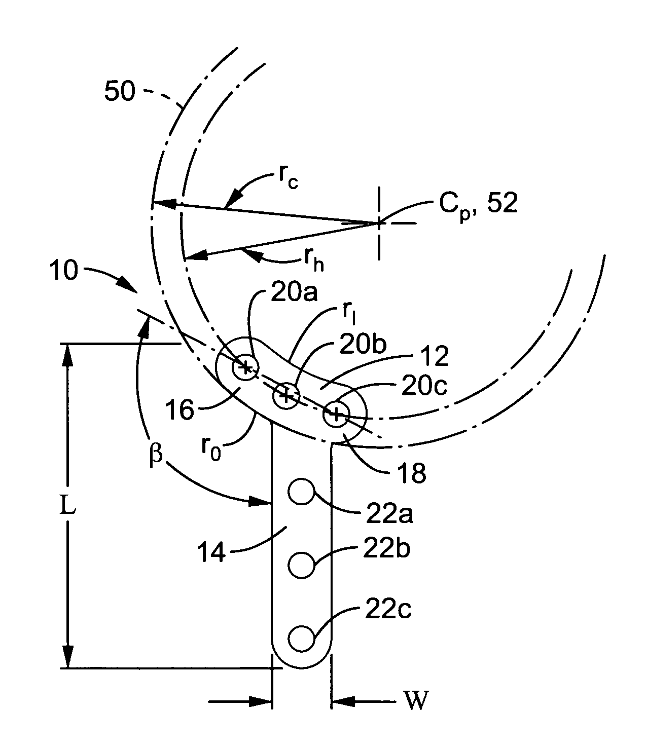
[0063] Referring to FIG. 3A, the bone plate 10 of the present invention may be subdivided into two portions: the proximal or top expanse 12 and the distal or bottom shank expanse 14. By way of example, the bone plate 10 is preferably made of a continuous piece of stainless steel, such as a sheet of 10-12 gauge SS 316 sheet metal. Other materials of similar stiffness and strength, such as titanium or titanium alloy may also be used.

[0064] The distal expanse 14 of bone plate 10 also has a plurality of mounting holes 22a,22b and 22c for mounting to the proximal tibia section 32. Gener...


PUM


Abstract

A bone fixation plate and methods are disclosed for performing an optimally centered tibial plateau leveling osteotomy. The optimally centered osteotomy produces a curvilinear cut separating a section of the tibia comprising the tibial metaphysis from a proximal section of the tibia, such that the curvilinear cut has a radial center point above the tibial plateau along the long axis of the tibia, and preferably in relation to the intersection of the cruciate ligaments. The bone fixation plate has a distal expanse configured to overlay the proximal section of the tibia along the length of the tibia. The distal expanse has a plurality of mounting holes to fix the distal expanse to the proximal section of the tibia. The bone fixation plate also has a proximal expanse configured to overlay the tibial metaphysis, the proximal expanse having a plurality of mounting holes; radially spaced apart substantially equidistant from a center point.

Description

CROSS-REFERENCE TO RELATED APPLICATIONS [0001] Not Applicable STATEMENT REGARDING FEDERALLY SPONSORED RESEARCH OR DEVELOPMENT [0002] Not Applicable INCORPORATION-BY-REFERENCE OF MATERIAL SUBMITTED ON A COMPACT DISC [0003] Not Applicable NOTICE OF MATERIAL SUBJECT TO COPYRIGHT PROTECTION [0004] A portion of the material in this patent document is subject to copyright protection under the copyright laws of the United States and of other countries. The owner of the copyright rights has no objection to the facsimile reproduction by anyone of the patent document or the patent disclosure, as it appears in the United States Patent and Trademark Office publicly available file or records, but otherwise reserves all copyright rights whatsoever. The copyright owner does not hereby waive any of its rights to have this patent document maintained in secrecy, including without limitation its rights pursuant to 37 C.F.R. § 1.14. BACKGROUND OF THE INVENTION [0005] 1. Field of the Invention [0006] Th...

Claims


Application Information

Patent Timeline
IPC IPC(8): A61B17/58
CPCA61B17/151A61B17/1728A61B17/8004A61B17/8061
Inventor CADMUS, CALVIN M.
Owner CADMUS CALVIN M
Why Eureka
Try Eureka