Point of load regulator having a pinstrapped configuration and which performs intelligent bus monitoring

a load regulator and pinstrap technology, applied in the direction of electric controllers, instruments, ignition automatic control, etc., can solve the problems of not being able to route high-current signals through the system, the power supply design is now a much more critical and difficult task, and the delivery of power is new and significant problems, so as to reduce the overall cost of implementation

Active Publication Date: 2006-07-06
INTERSIL INC
View PDF28 Cites 223 Cited by
  • Summary
  • Abstract
  • Description
  • Claims
  • Application Information

AI Technical Summary

Benefits of technology

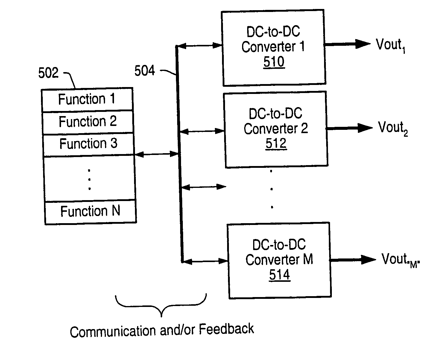
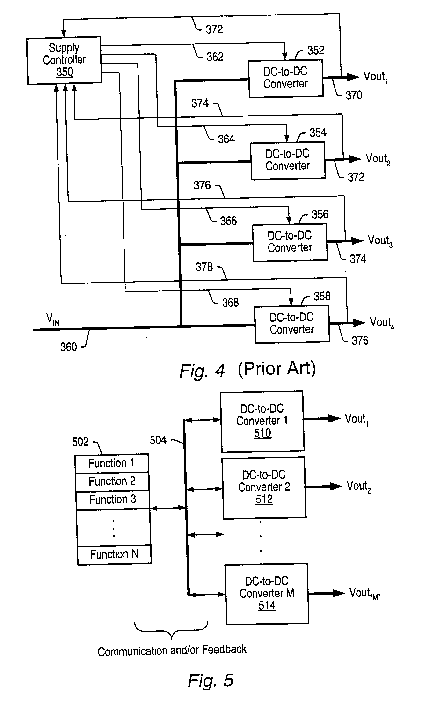
[0041] The present invention relates to a new way to control, configure, monitor and manage DC power distribution in modern electronic systems. Specifically, in one embodiment the present invention provides a new system-level approach to managing the delivery of DC voltage and / or current. Several system level functions may be enabled without requiring separate ICs to perform those functions. In one set of embodiments the system comprises several control chips and a novel way of enabling the control chips to communicate with each other. In one embodiment the system couples a group of control chips in a configuration that reduces the overall cost of implementing the common features required in advanced electronic systems. The system may be expandable and may include some inherent reliability features. One set of embodiments is particularly suited for use in rack-based electronics and computer servers; however, alternate embodiments may be equally applicable to smaller and portable electronics, automotive systems and motor control applications.

Problems solved by technology

This rapid evolution has created new and significant problems in delivery of the power to and removal of waste heat from these ICs.
Power supply design is now a much more critical and difficult task than it was a few years ago.
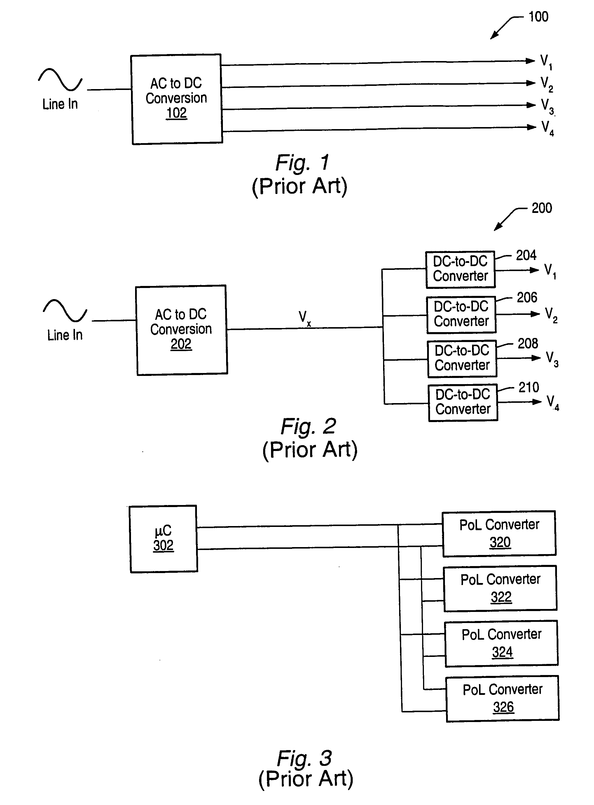
However, it may not be practical to route high-current signals throughout a system.
In many power distribution systems it is typically not enough to just distribute power around a system to the various POLs.
Dense electronic systems often generate excessive waste heat.
Routing of such signals is often difficult, while no true communication is established between various POL converters and / or between the POL converters and any other elements of the system.
In general, microcontroller 302 checks status for one POL converter at a time, which may be viewed as a disadvantage when more interactive, real-time communication is desired in a system.
Some analog converters available today already contain some of the functions, for example current share and / or tracking, but these functions are still unique to the converters, do not take into consideration system level requirements, and typically still require to be configured individually per function in the system.
This approach incorporates the traditional partitioning along analog and digital boundaries, and typically leads to redundancy and complicated routing requirements in a system.

Method used


Image

  • Point of load regulator having a pinstrapped configuration and which performs intelligent bus monitoring
  • Point of load regulator having a pinstrapped configuration and which performs intelligent bus monitoring
  • Point of load regulator having a pinstrapped configuration and which performs intelligent bus monitoring

Examples


Embodiment Construction

[0059] As used herein, a “trigger” signal is defined as a signal that is used to initiate, or “trigger”, an event or a sequence of events in a digital system. A trigger signal is said to be in a “triggering state” at a time when it initiates a desired event, or sequence of events. A periodic trigger signal may commonly be referred to as a “clock”. In a “synchronous” digital system, generally a clock, commonly referred to as a “system clock”, may be used for initiating most events, or sequences of events. An example of a triggering state may be, but is not limited to, a rising edge of a pulse of a clock in a synchronous digital system. A “frequency” of pulses refers to a number of pulses that may appear within a selected unit period of time. For example, if twenty pulses appear within duration of one second, then the frequency of the pulses is 20 Hz.

[0060] When an event, or a sequence of events, is said to be initiated “in response to” receiving a stimulus signal, it may be implied ...


PUM


Abstract

A new system-level approach to managing the delivery of DC voltage and current. Several system level functions may be enabled without requiring separate ICs to perform those functions. Supervisory functions for a voltage converter may be performed by a central control module or chip that may be coupled to point-of-load voltage converters comprised in digital power management devices (DPMD) through a serial digital bus. The DPMDs may also use the high-speed serial digital bus to provide real-time feedback information to the central control module or chip. Single DPMDs may be combined together in a current sharing configuration in a “plug-and-play” fashion, where the control logic in each DPMD is capable of automatically establishing control loops required a multi-phase supply. Feedback necessary for establishing control may be transmitted across the digital bus coupling the devices. The supervisory functions may be included in each DPMD, which may communicate with each other over a serial digital bus, where the DPMDs singly or together may operate to perform control of their respective POLs, enabling configurations that do not require a central control module.

Description

PRIORITY CLAIM [0001] This application is a continuation of co-pending application Ser. No. 10 / 820,976 filed on Apr. 8, 2004 titled “Method And Apparatus For Improved DC Power Delivery, Management And Configuration”, whose inventor was James W. Templeton, which claims benefit of priority of provisional application Ser. No. 60 / 462,414 titled “Method And Apparatus For Improved DC Power Delivery, Management And Configuration” and filed Apr. 11, 2003, which are both hereby incorporated by reference as though fully and completely set forth herein.BACKGROUND OF THE INVENTION [0002] 1. Field of the Invention [0003] The present invention relates generally to power systems. More specifically, the present invention provides an improved method and apparatus for DC power delivery, management and configuration. [0004] 2. Description of the Related Art [0005] From 1995 to 2001, the highest density processors from manufacturers such as Intel went from a power consumption rate of about 30 Watts at ...

Claims


Application Information

Patent Timeline
Patent Type & Authority Applications(United States)
IPC IPC(8): G05B11/01H02J1/10H02J13/00
CPCH02J1/102H02J13/0003H02J1/001H02J13/00002H02J13/00016Y04S10/30Y02E60/00
Inventor TEMPLETON, JAMES W.
Owner INTERSIL INC
Why Eureka
Try Eureka