Cutter bar
a technology of cutter bars and guide plates, applied in the field of cutter bars, can solve the problems of increased cutting force, friction between the knife and the guide plate, and large wear on the knife bar and the guide plate, and achieve the effect of long li
- Summary
- Abstract
- Description
- Claims
- Application Information
AI Technical Summary
Benefits of technology
Problems solved by technology
Method used
Image
Examples
first embodiment
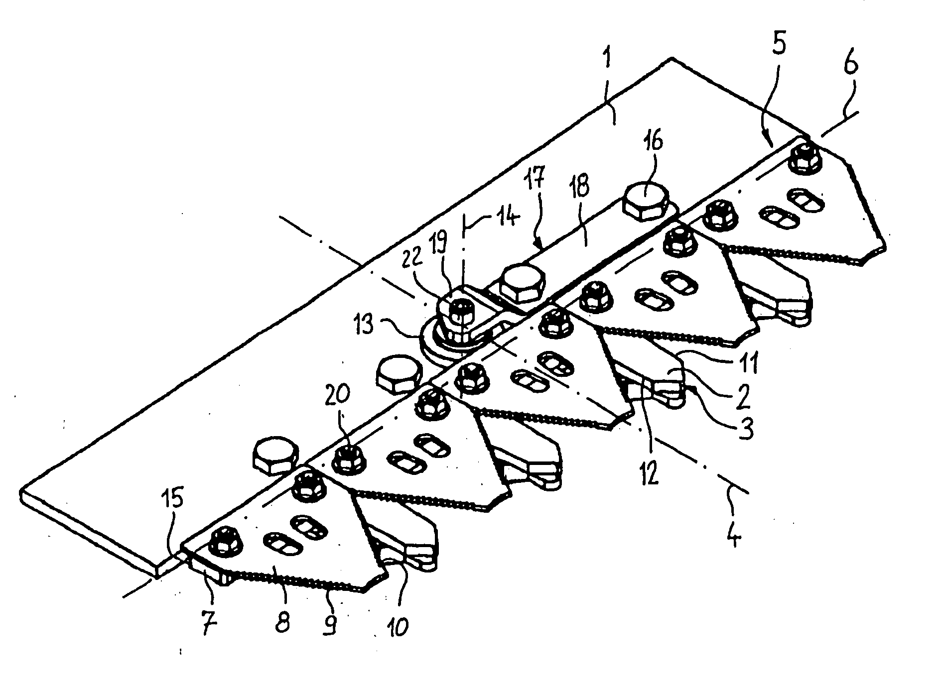
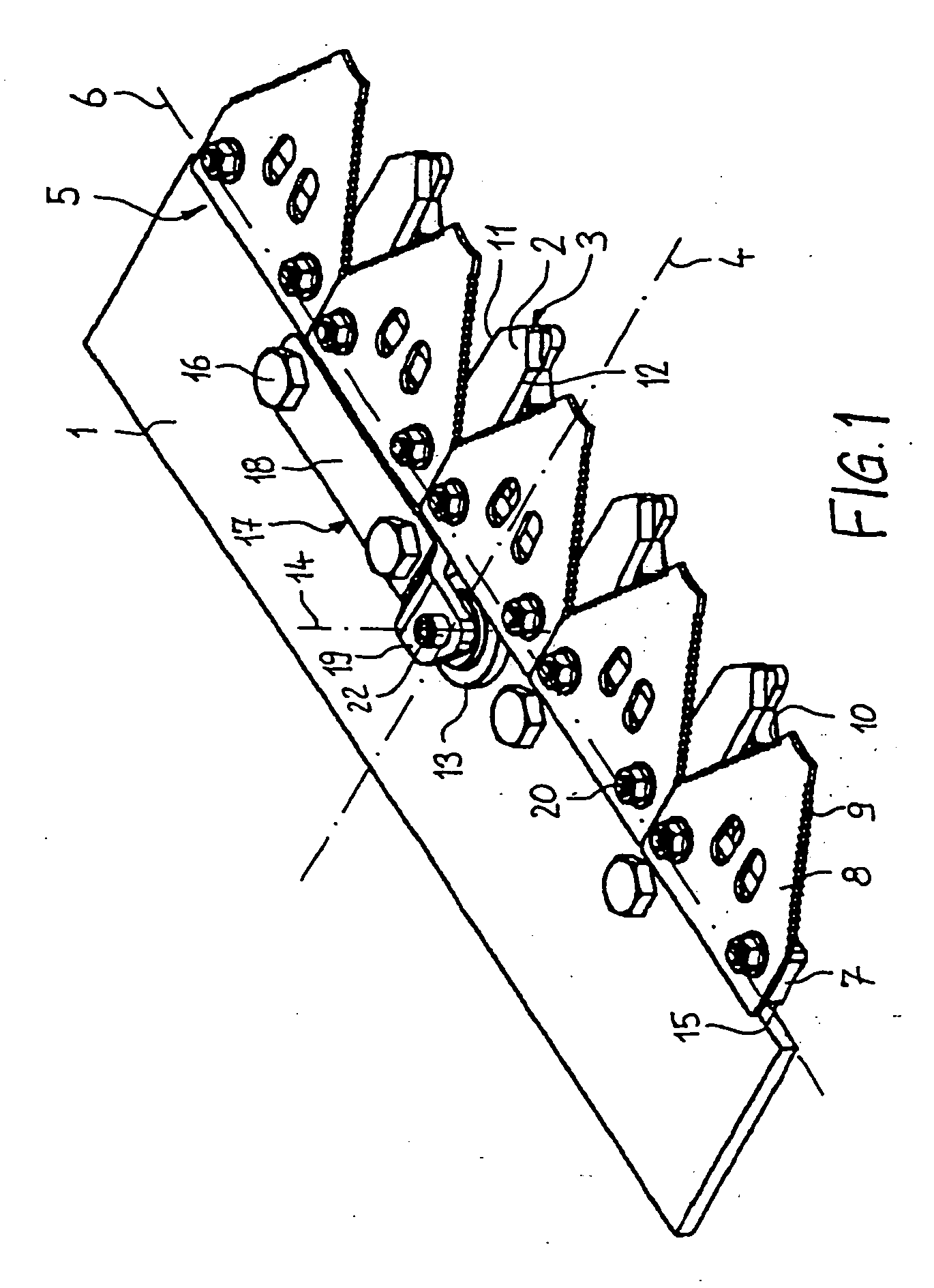
[0028]FIG. 1 illustrates a cutter bar according to the invention. The cutter bar has a finger bar 1, attached on an agricultural implement. Reaping fingers 2 are arranged on the cutter bar 1. The free ends 3 of the reaping fingers 2 point in the working direction of the agricultural implement and are arranged parallel to a longitudinal axis 4. A knife 5 is reciprocatingly movably guided along a transverse axis 6 relative to the finger bar 1. The transverse axis 6 extends at a right angle to the longitudinal axis 4. The knife 5 includes a knife bar 7 as well as several blades 8. The blades 8 are supported on each other in the direction of the transverse axis 6. The blades 8 form, respectively, a first cutting edge 9 and a second cutting edge 10. The first cutting edges 9 interact, respectively, with at least one first counter cutting edge 11 of a reaping finger 2. The second cutting edges 10 also interact, respectively, with at least one second counter cutting edge 12 of the reaping ...
second embodiment
[0037] Unlike the second embodiment, the roller holder 217 is formed shorter and is attached by a fixing screw 216 to one of the reaping fingers 202 on the top of the reaping finger 202.
[0038] A fourth embodiment is illustrated in FIGS. 6 and 7. Components, which correspond to components of the first embodiment, are provided with reference numerals, which are increased by the numerical value 300.
fourth embodiment
[0039] In the fourth embodiment, the roller holders 317 are in the form of bridges. The roller holders 317 are arranged between neighbouring reaping fingers 302, 302′, 302″. The roller holders 317 are fixed by fixing screws 316 of the neighbouring reaping fingers 302, 302′, 302″.
[0040] Furthermore, one of the rollers has a first collar 321. The blades 308 are supported vertically downwards against the first collar 321. A roller 313′, arranged next to the roller 313, has a second collar 325. The blades 308 are vertically supported upwards against the second collar 325. Thus, this ensures an improved guide of the knife 305.
[0041] Alternatively, all rollers can have, respectively, a first collar and a second collar. Thus, the blades are supported vertically downwards as well as vertically upwards on each roller. Further, the reaping fingers can be arranged vertically below the finger bar. Also, the roller holders can be arranged vertically below the reaping finger.
PUM
 Abstract
Description
Claims
Application Information
 - R&D
- Intellectual Property
- Life Sciences
- Materials
- Tech Scout
- Unparalleled Data Quality
- Higher Quality Content
- 60% Fewer Hallucinations
Browse by: Latest US Patents, China's latest patents, Technical Efficacy Thesaurus, Application Domain, Technology Topic, Popular Technical Reports.
© 2025 PatSnap. All rights reserved.Legal|Privacy policy|Modern Slavery Act Transparency Statement|Sitemap|About US| Contact US: help@patsnap.com


