Steering device

a technology of steering device and steering angle, which is applied in the direction of mechanical control device, coupling, instrument, etc., can solve the problems of complicated operation and restricted degree of freedom for setting the steering angle ratio, and achieve the effect of compact configuration and light weigh

Inactive Publication Date: 2006-07-13
NSK LTD +1
View PDF9 Cites 19 Cited by
  • Summary
  • Abstract
  • Description
  • Claims
  • Application Information

AI Technical Summary

Benefits of technology

[0005] It is an object of the present invention to provide a steering apparatus capable of arbitrarily changing, though light in

Problems solved by technology

When at such a steering gear ratio, however, the steering wheel is required to make a large number of rotations during low-speed traveling such as putting the vehicle in the garage, and th

Method used


Image

  • Steering device
  • Steering device
  • Steering device

Examples


first embodiment

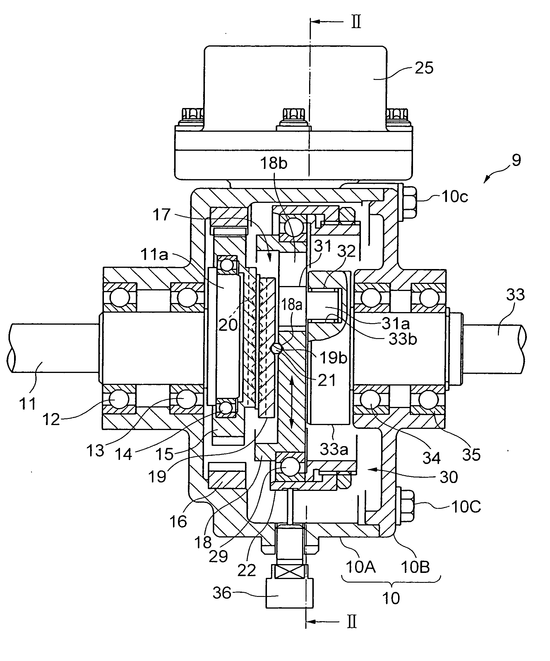
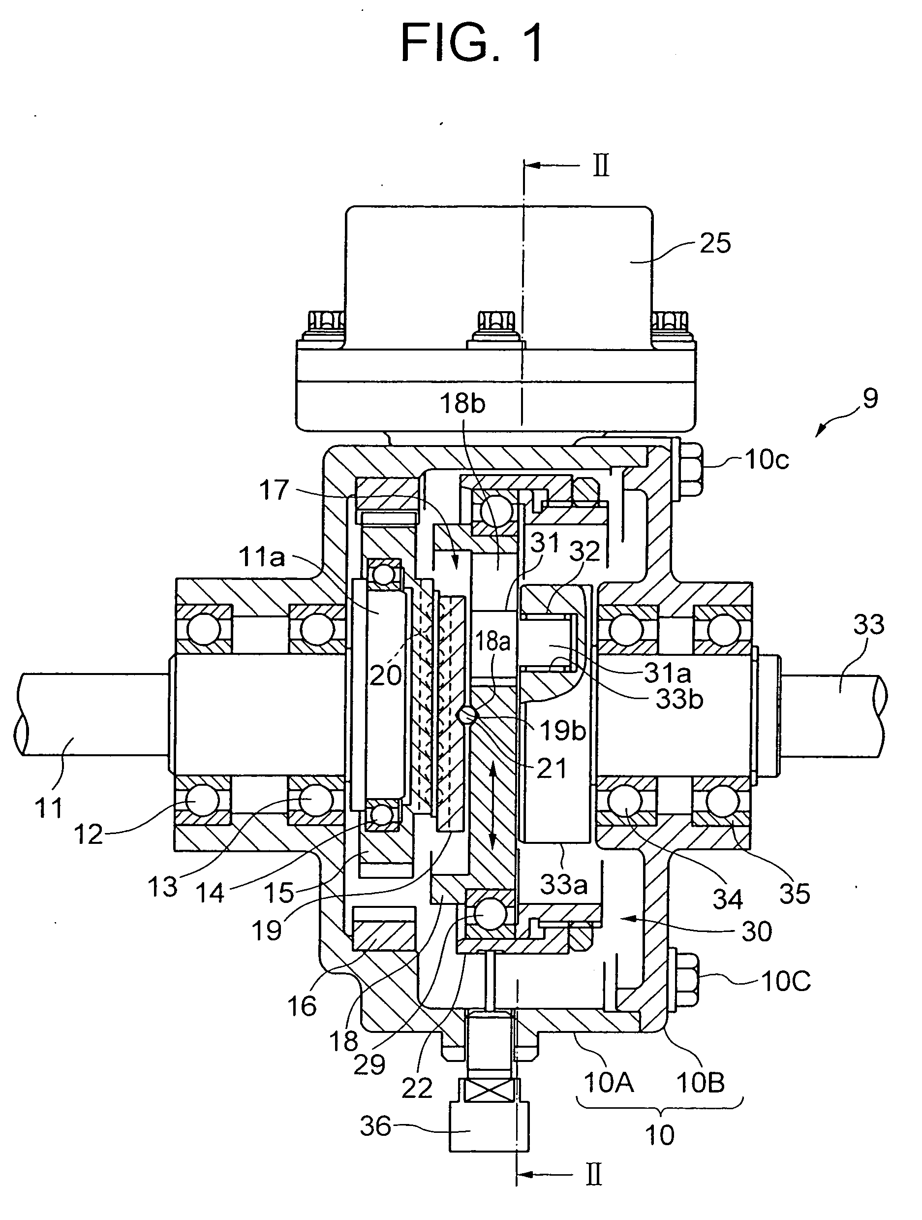
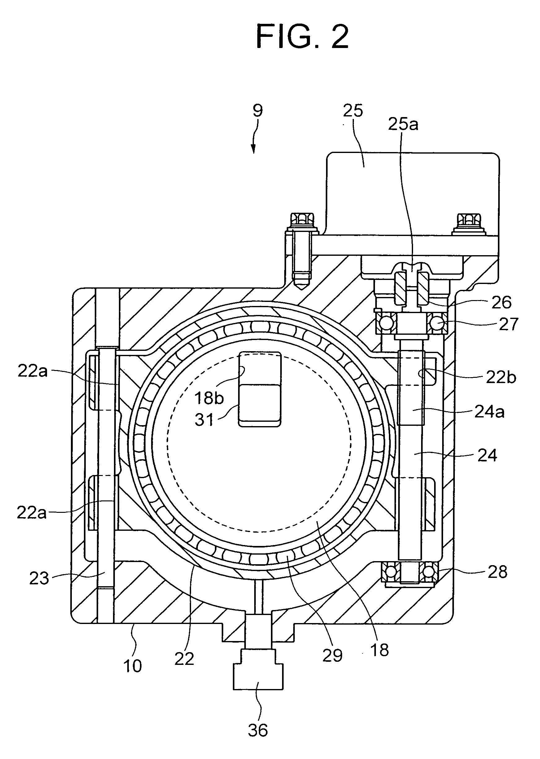
[0021]FIG. 1 is a sectional view of a variable steering gear ratio mechanism (power transmission mechanism) 9 that can be built in a steering apparatus according to the FIG. 2 is a sectional view of the configuration cut off along the line II-II in FIG. 1 as viewed in an arrow direction. Housing 10 is constructed of a housing body 10A and a cover member 10B fixed to the housing body 10A by a bolt 10C. In FIG. 1, an input shaft 11 connected to an unillustrated steering shaft is so supported by bearings 12, 13 as to be rotatable along within the housing body 10A. A large-diameter disc portion 11a is formed in a way that deviates an axis line at a right side end of the input shaft 11 in FIG. 1. The large-diameter disc portion 11a rotatably supports an external gear (first external gear) 15 through a bearing 14.

[0022] The external gear 15 meshes with an internal gear (first internal gear) 16 fixed to the housing 10. The external gear 15 and the internal gear 16 configure a hypocycloid ...

second embodiment

[0037]FIG. 7 is a sectional view of a variable steering gear ratio mechanism according to a A variable steering gear ratio mechanism 109 shown in FIG. 7 is different from the construction illustrated in FIG. 1 in terms of providing the speed increasing mechanism, so that the components exhibiting the common functions are marked with the same numerals and symbols, wherein the discussion will be focused mainly on the different points.

[0038] The large-diameter disc portion 11a formed in a way that deviates an axis line at a right side end of the input shaft 11 in FIG. 7, rotatably supports the external gear 15 through the bearing 14. The external gear 15 meshes with the internal gear 16 fixed to the housing 10. The external gear 15 and the internal gear 16 configure the hypocycloid speed reducing mechanism. The external gear 15 is connected via the Oldham coupling (first Oldham coupling) 17 to an intermediate member 140 so supported by a bearing 141 as to be rotatable along within the...


PUM


Abstract

A variable steering gear mechanism (9) is constructed of an external gear (15) connected to an input shaft (11), an internal gear (16) fixed to housing (10) and meshing with the external gear (15), an intermediate member (19) receiving a rotary force transmitted from the external gear (15), change means (18a, 31, 33a) capable of changing a rotation ratio of the output shaft (33) to a rotation of a guide member (18), and an Oldham coupling (17) connecting the intermediate member (19) to the guide member (18). When a speed reduction ratio thereof is set to, e.g., 6:1, it follows that the input member (18) of the change means makes a ¼ rotation (rotates through 90 degrees) during one-sided 1.5 rotations (540 degrees) of the input shaft (11), whereby a characteristic of the change means can be effectively utilized. A gear mechanism such as a hypocycloid mechanism has a characteristic capable of, though compact in configuration, obtaining a speed reduction ratio as large as 6:1, and also such a characteristic that the external gear (15), in addition to the self-rotation, revolves around the axis line of the internal gear (16), i.e., rotates while being eccentric. By contrast, according to the present invention, the use of the Oldham coupling (17) enables only the self-rotation to be extracted and transmitted by absorbing the eccentricity of the external gear (15). Additionally, a meshing length between the external gear (15) and the internal gear (16) becomes large, whereby smoother power transmission can be attained.

Description

TECHNICAL FIELD [0001] The present invention relates to generally to a steering apparatus, more particularly to a steering apparatus capable of changing a steering gear ratio, and further to a vehicle power steering apparatus employing an electric motor. BACKGROUND ARTS [0002] Known in the vehicle is a steering apparatus wherein a steering gear ratio (a steered angle of a tire with respect to a rotational angle of a steering wheel, which is also called a total gear ratio) is fixed. In the case of the steering apparatus having a 1-to-1 relationship between the rotational angle of the steering wheel and the steered angle of the tire, the steering gear ratio is set exclusively for ensuring high-speed stability of the vehicle. Namely, the steering gear ratio is set large in many cases so that the vehicle does not sensitively respond during high-speed traveling. When at such a steering gear ratio, however, the steering wheel is required to make a large number of rotations during low-spee...

Claims


Application Information

Patent Timeline
IPC IPC(8): B62D5/04B62D3/02B62D1/16B62D5/22F16D3/04
CPCY10T74/20498B62D1/166
Inventor CHIKARAISHI, KAZUO
Owner NSK LTD
Why Eureka
Try Eureka