Electric drive device for vehicle and hybrid engine/motor-type four wheel drive device

a technology of electric drive and hybrid engine, which is applied in the direction of motor/generator/converter stopper, multiple dynamo-motor starters, dynamo-electric converter control, etc., can solve the problems of large number of electric parts, large capacitance of capacitors, and high cost, so as to reduce cost, simplify and miniaturize electric parts, and maintain performan

Inactive Publication Date: 2006-07-13
HITACHI LTD +1
View PDF4 Cites 59 Cited by
  • Summary
  • Abstract
  • Description
  • Claims
  • Application Information

AI Technical Summary

Benefits of technology

[0013] An object of the present invention is to provide a hybrid engine-motor type vehicle drive system realizing simplification and miniaturization of electric parts and, moreover, capable of intending to reduction in cost while maintaining performances, and is to provide an electric drive system for a vehicle which can be used for the same. In particular, in a hybrid engine-motor type four-wheel drive system, an electric drive system for a vehicle realizing a single generator and a single battery is provided.

Problems solved by technology

Consequently, the number of electric parts is large and the cost is high.
Also in the case of using a capacitor as a power supply for the wheel drive motor that accumulates regenerative power, there is still a problem that the capacitor has a large size to have capacitance according to the high-voltage specification of about 250 to 300V.
If power from the battery for accessories (for example, specification of 12V) is supplied to the field winding of the generator for driving wheels at the time of starting the engine so as to realize a single battery, the following problem occurs.
For example, in the case of making the generator for driving wheels generate power by supplying power of the battery for accessories to the field windingince the field current is small, when the engine speed is low on starting of the vehicle or the like, sufficient generator output cannot be obtained.
Accordingly, power of the motor for driving wheels cannot be sufficiently ensured.
Even if the drive power is provided to the motor upon starting of the vehicle by using the generator for the wheel drive motor, when the engine speed is low on starting of the vehicle, the power of the motor drive cannot be sufficiently ensured.

Method used


Image

  • Electric drive device for vehicle and hybrid engine/motor-type four wheel drive device
  • Electric drive device for vehicle and hybrid engine/motor-type four wheel drive device
  • Electric drive device for vehicle and hybrid engine/motor-type four wheel drive device

Examples


embodiment 1

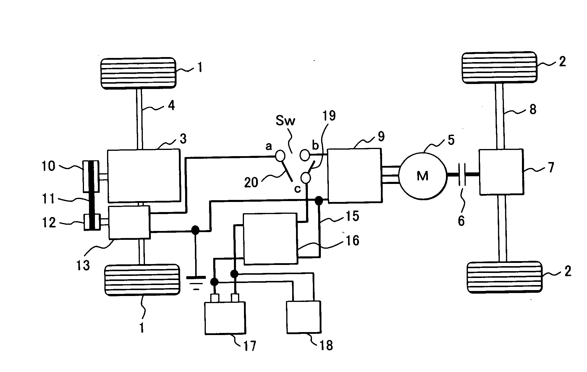
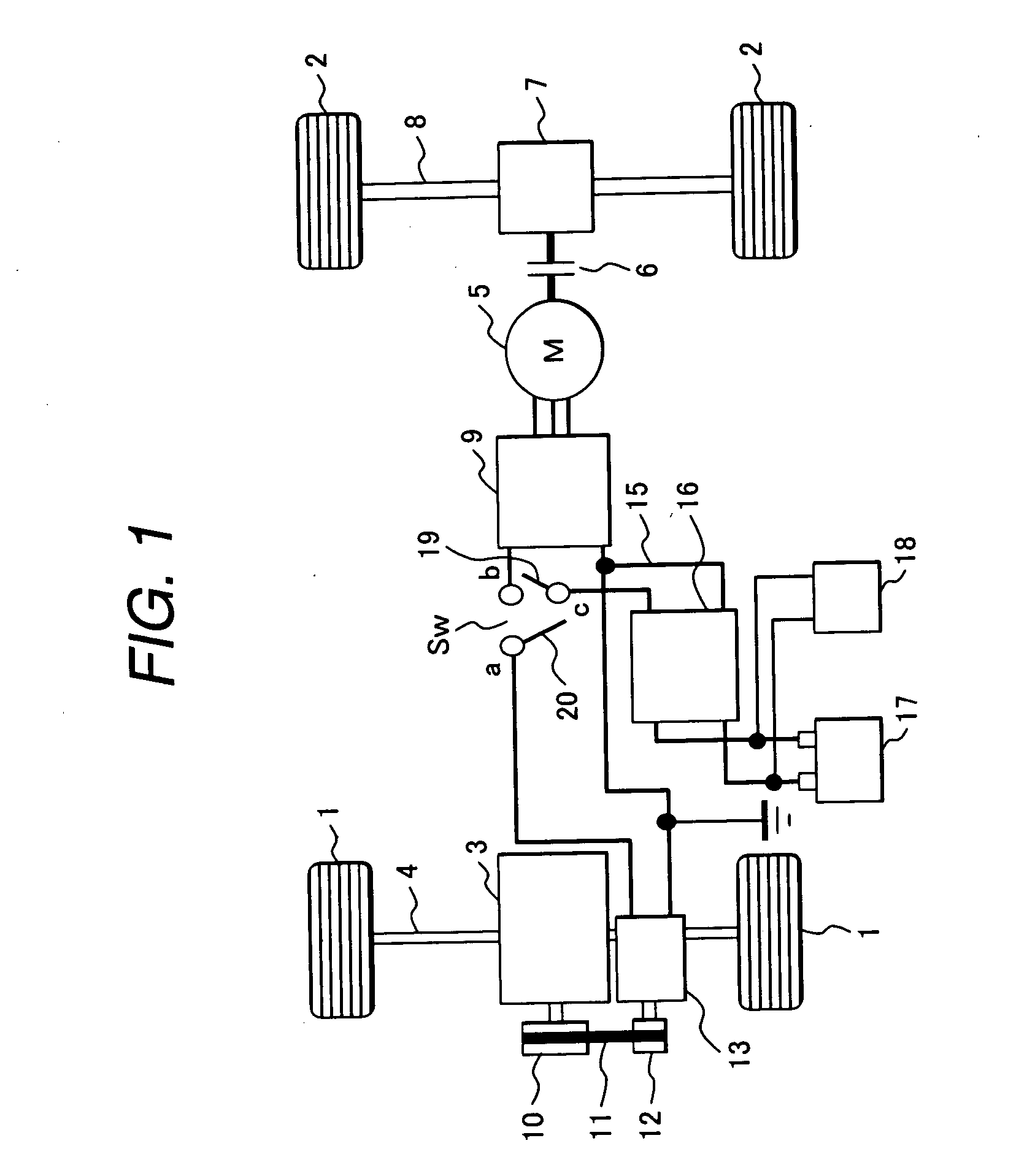
[0049]FIG. 1 is a configuration diagram of a vehicle drive system of a hybrid engine / motor type vehicle drive system to which an electric drive system for a vehicle according to an embodiment of the invention is applied.

[0050] For example, either front wheels 1 or rear wheels 2 (here, the front wheels is cited) are driven by an engine 3 (irrespective of the kind of the engine). The other wheels (in this case, rear wheels) are driven by a motor 4.

[0051] A power of the engine 3 is transmitted to a transmission (not shown) and a front-wheel axle 4 to drive a pair of front wheels 1.

[0052] A torque of the motor 5 is transmitted to a rear wheel axle 8 via a clutch 6 and a differential gear 7 to drive a pair of rear wheels 2.

[0053] The rear wheels 2 are driven by driving the motor 4 as necessary (drive conditions).

[0054] In the embodiment, a three phase alternating current motor (AC motor) driven by an inverter 9 is used as an example of the motor 5. A motor / generator for generating n...

second embodiment

[0340] A second embodiment of the invention will be described with reference to FIGS. 18 to 21.

[0341]FIG. 18 shows a hybrid engine-motor type vehicle drive system to which the vehicle electric drive system according to the second embodiment of the invention is applied. FIG. 19 shows the system configuration of the vehicle electric drive system of the second embodiment including a 4WD control unit. FIG. 20 shows a functional configuration of a microprocessor unit as a component of the 4WD control unit. FIG. 21 shows operation timings in a vehicle operating state of components of the vehicle electric drive system of the second embodiment.

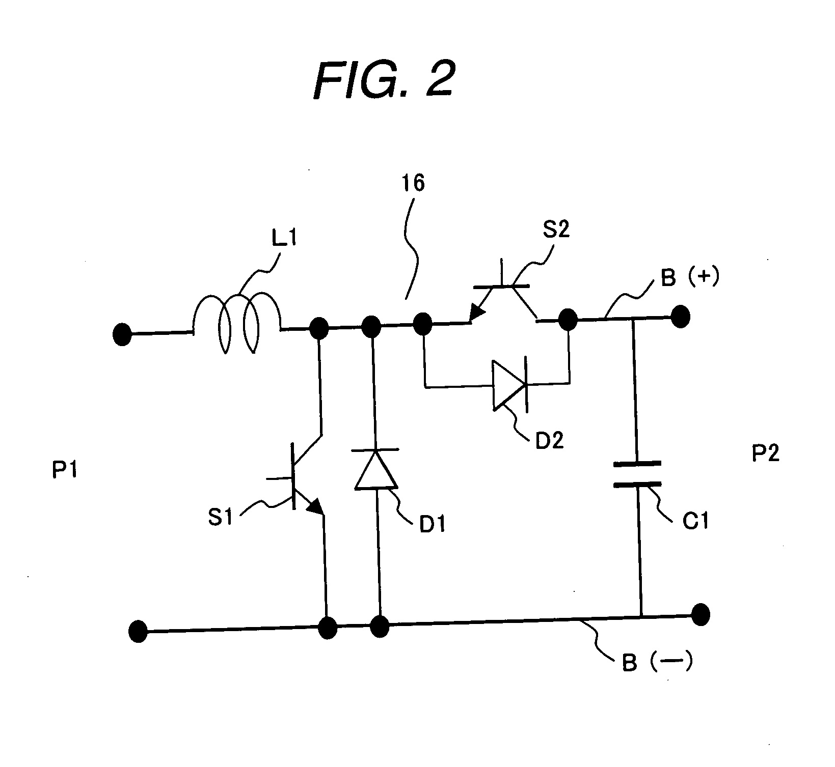
[0342] In the second embodiment, the DC / DC converter 16 is disposed in a position different from that in the first embodiment, that is, between the inverter 9 and the relay 20. In the second embodiment, as the alternator 13, a conventional alternator for charging accessories is used. The alternator 13 is controlled by the ECU 90 and outputs the powe...

third embodiment

[0486]FIG. 22 is a circuit diagram of a vehicle electric drive system according to an embodiment of the invention. FIG. 23 is a schematic diagram of a Hybrid engine-motor type four-wheel drive system to which the vehicle electric drive system is applied.

[0487] First, the outline of the hybrid engine-motor type four-wheel drive system will be described with reference to FIG. 23.

[0488] It is assumed that either the front wheels 101 or rear wheels 102 (in this case, front wheels) are driven by an engine 103 (the engine may be any kind) and the other wheels (in this case, rear wheels) are driven by a motor 104.

[0489] That is, the engine 103 transmits its power to a transmission 105 and the front wheel-axle to drive the pair of front wheels 1. The motor (DC motor) 104 transmits its power to the rear wheel-axle via a clutch 130 and a differential gear 106 to drive the rear wheels 102.

[0490] The rear wheels 102 are driven by driving the motor 104 as necessary (according to drive condit...


PUM


Abstract

A vehicle electric drive system and a hybrid engine-motor type vehicle drive system realizing simplification and miniaturization of electric parts and, moreover, reduction in cost while maintaining performances can be provided. A part 1 of wheels is driven by an engine. The wheels are driven by a motor as necessary. The motor, a generator, and an accessory battery are connected to each other via a voltage step-up / step-down device. The voltage step-up / step-down device has a function of stepping up power of the battery and supplying the stepping up power to the motor, and a function of stepped down power of the generator and supplying the stepped down power to the battery and the accessories.

Description

TECHNICAL FIELD [0001] The present invention relates to an electric drive system for a vehicle. To be more specific, it is suitable for vehicle in which a part of wheels are driven with an engine and other wheels are driven with a motor. For example, it relates to hybrid engine-electric motor type four-wheel drive system. BACKGROUND ART [0002] A hybrid engine-electric motor type four-wheel drive system is known in conventional vehicle drive system field. In the drive system, either a frond wheel drive-axle or a rear wheel drive-axle (here, the front wheel drive-axle is cited as an example of that, and it will be also called as “front wheels” below) is driven by an internal combustion engine, and the other (here, the rear wheel drive-axle is cited as an example of that, and it will be also called as “rear wheels” below) is driven by a motor as necessary. [0003] Four-wheel drive mode in which both of the engine and motor are used as a power source is performed under heavy-load conditi...

Claims


Application Information

Patent Timeline
Patent Type & Authority Applications(United States)
IPC IPC(8): H02P5/00H02P1/00H02P3/00B60L50/16
CPCB60K6/26B60K6/44B60K6/52Y02T10/70Y02T10/623Y02T10/6265Y02T10/7077B60L11/14B60L50/16Y02T10/62Y02T10/7072
Inventor TAHARA, KAZUONISHIDATE, KEISUKEYOSHIDA, KENICHISHIMIZU, HISAYAINNAMI, TOSHIYUKIFUJINO, SHINICHI
Owner HITACHI LTD
Why Eureka
Try Eureka