Determining dead times in switched-mode DC-DC converters

a converter and dead time technology, applied in the direction of electric variable regulation, process and machine control, instruments, etc., can solve the problems of large current spikes through the device, severe degradation of efficiency, and more adverse penalties for converter efficiency, so as to improve the efficiency of switched-mode dc-dc converters, improve the efficiency of dc-dc converters, and achieve near-optimum efficiency of converters. , the effect of improving the efficiency of dc-dc converter

Active Publication Date: 2006-07-13
UNIV OF COLORADO THE REGENTS OF
View PDF5 Cites 130 Cited by
  • Summary
  • Abstract
  • Description
  • Claims
  • Application Information

AI Technical Summary

Benefits of technology

[0014] It is desirable to be able to determine dead-times that increase the efficiency in switched-mode DC-DC converters with synchronous rectifiers or other complementary switching devices in simpler, faster, and / or more accurate implementations than were previously known. The dead-times of a converter, for example, can be adjusted to values that result in a near-optimum efficiency of the converter.

Problems solved by technology

Too short (or negative) dead-times may result in simultaneous conduction of the main power switch 110 and the synchronous rectifier power switch 112, resulting in large current spikes through the devices and even more adverse penalties in the converter efficiency.
In the presence of parameter tolerances, temperature variations or operating point changes, this simplest approach of fixed dead times often yields severely degraded efficiency, especially in converters operating at relatively high switching frequencies (in the hundreds of kHz to megahertz range).
In “adaptive” gate-drive schemes, fast comparators attempt to match the zero-crossing of the voltage vs and the threshold-crossing instants in each switching cycle, which in practice results in sub-optimal performance because of the comparator delays and sensitivity to parameter and temperature variations.
They are still based on sensing the noisy switch voltage vs, and on the ability to accurately detect and control turn-on and turn-off instants, which can be difficult, especially if the gate drivers and the power MOSFETs are not integrated on the same die.
Although possible in principle, these approaches require sensing or computing the input power or losses, which are difficult to accomplish in practice.
Actually measuring the input current, however, is often difficult to implement due to noisy input current sensing conditions, lengthy time durations required to average the input currents, complicated high-resolution current sensing circuitry, and sensitivity due to input-current variations caused by disturbances other than dead-times.

Method used


Image

  • Determining dead times in switched-mode DC-DC converters
  • Determining dead times in switched-mode DC-DC converters
  • Determining dead times in switched-mode DC-DC converters

Examples


Embodiment Construction

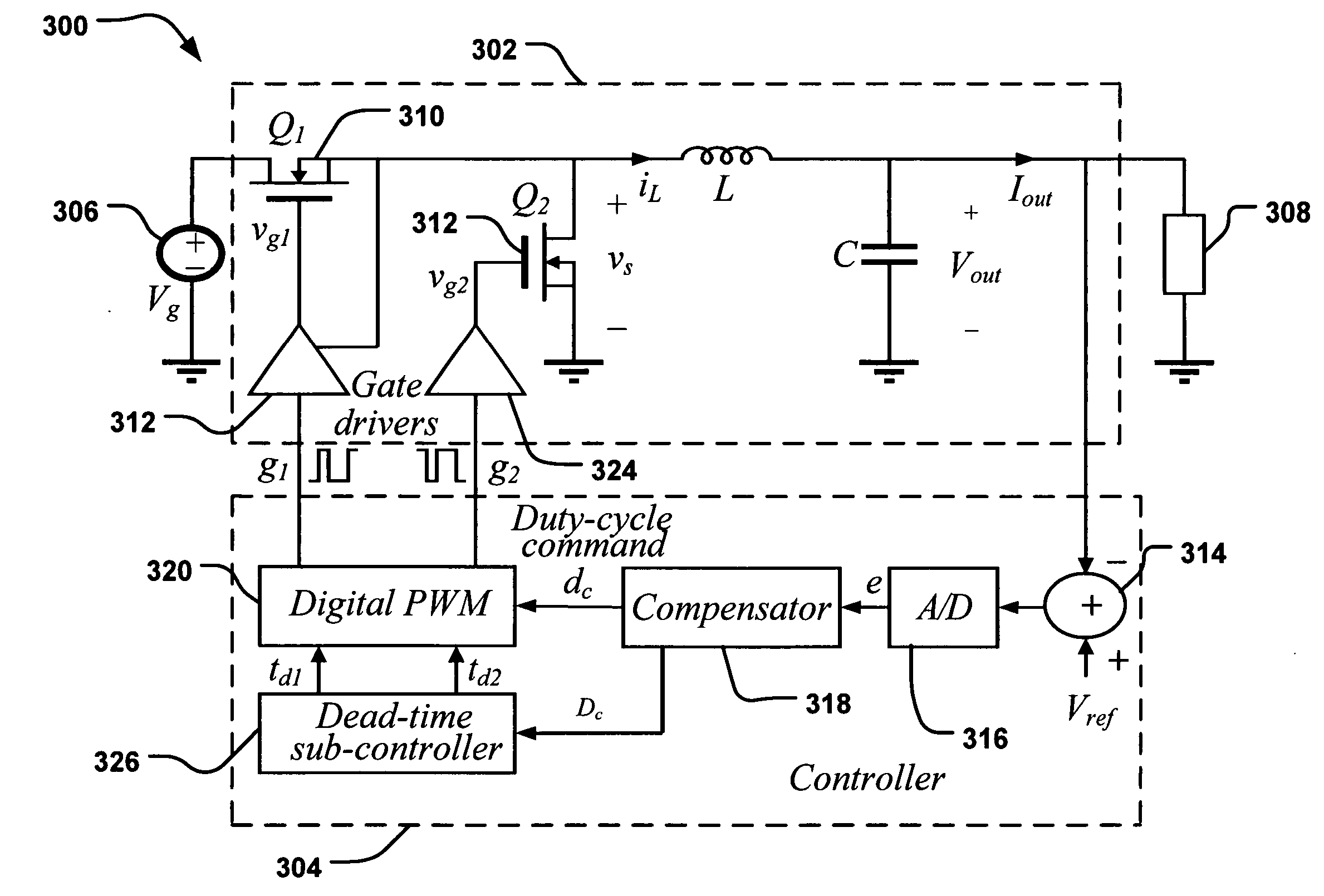
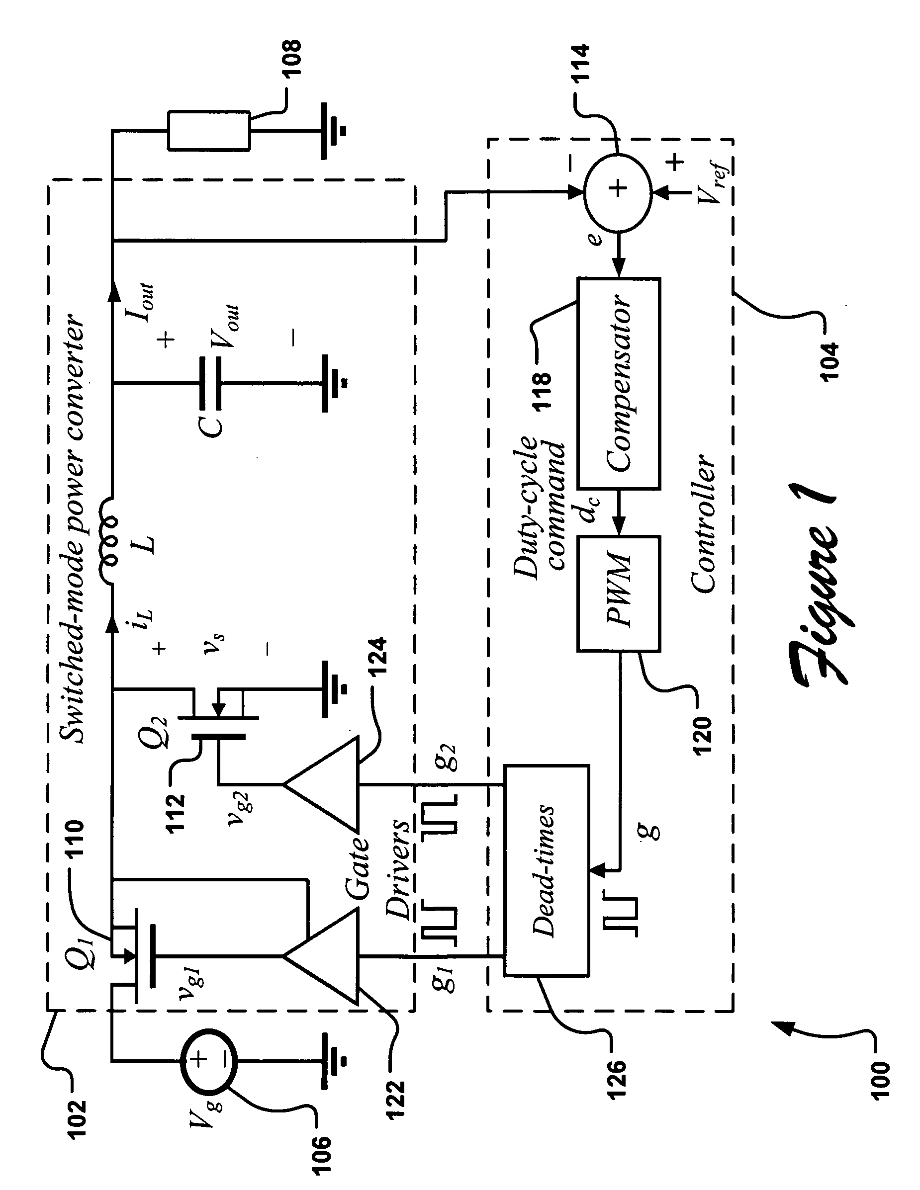
[0037] Controllers for use in determining dead-times of control signals for switched-mode DC-DC converters comprising synchronous rectifiers or other complementary switching devices are provided. While particular implementations of controllers and DC-DC converters are described in particular detail, one skilled in the art would readily recognize that other types of converters and controllers may be used within the scope of the present invention. For example, a controller may be implemented in (1) any number of hardware implementations using custom digital logic, such as in digital logic implemented on one or more programmable logic chips (e.g. a field programmable gate array (FPGA) or complex programmable logic devices (CPLD)), application specific integrated circuits, or custom digital or mixed-signal controller chips; (2) any number of software implementations, such as using microcontrollers, microprocessors, or digital signal processors (DSP) that execute a dead-time determinatio...


PUM


Abstract

Systems, methods, and apparatuses are disclosed for determining dead-times in switched-mode DC-DC converters with synchronous rectifiers or other complementary switching devices. In one embodiment, for example, a controller for a DC-DC converter determines dead-times for switching devices of a synchronous rectifier or other complementary switching device of the converter in which a dead-time is derived from an output voltage or current that is already sensed and used in the output regulation of the converter. In another embodiment, a controller is provided for controlling a switched-mode DC-DC converter comprising a pair of power switches. The controller comprises an input, a reference generator, a comparator, a compensator, a dead-time sub-controller, and a modulator. In another embodiment, the controller may adjust the dead-times during the operation of the converter to adjust periodically and/or in response to changes in operating conditions. In addition, methods of determining dead-times of control signals for a switched-mode DC-DC converter comprising a pair of power switches and of controlling a DC-DC converter are also disclosed.

Description

CROSS-REFERENCE TO RELATED APPLICATIONS [0001] This application claims the benefit of U.S. provisional application Nos. 60 / 632,804 entitled “Sensorless Optimization of Dead Times in Switched-mode DC-DC Converters with Synchronous Rectifiers” and filed on Dec. 3, 2004 and 60 / 655,233 entitled “Sensorless Optimization of Dead Times 2” and filed on Feb. 20, 2005, which are both hereby incorporated by reference as though fully set forth herein.BACKGROUND OF THE INVENTION [0002] a. Field of the Invention [0003] The instant invention relates to DC-DC converters with synchronous rectifiers or other complementary switching devices. In particular, the instant invention relates to a method, system, and apparatus for determining dead times in DC-DC converters with synchronous rectifiers or other complementary switching devices. [0004] b. Background Art [0005] Because of significantly lower conduction losses compared to diode rectifiers, synchronous rectifiers are now used in essentially all low...

Claims


Application Information

Patent Timeline
Patent Type & Authority Applications(United States)
IPC IPC(8): G05F1/40G05F1/56
CPCH02M1/38H02M3/1588Y02B70/1466Y02B70/10
Inventor MAKSIMOVIC, DRAGANYOUSEFZADEH, VAHID
Owner UNIV OF COLORADO THE REGENTS OF
Why Eureka
Try Eureka