Switching circuit for an electromagnetic source for the generation of acoustic waves

a technology of electrical circuit and electromagnetic source, which is applied in the direction of mechanical vibration separation, electrical apparatus, coupling devices, etc., can solve the problems of high cost of variable capacitance capacitor c and variable capacitance capacitor coil l, and achieve the improvement of calculi disintegration effect and the increase of the lifespan of the first and second capacitors

Inactive Publication Date: 2006-07-13
SIEMENS AG
View PDF3 Cites 64 Cited by
  • Summary
  • Abstract
  • Description
  • Claims
  • Application Information

AI Technical Summary

Benefits of technology

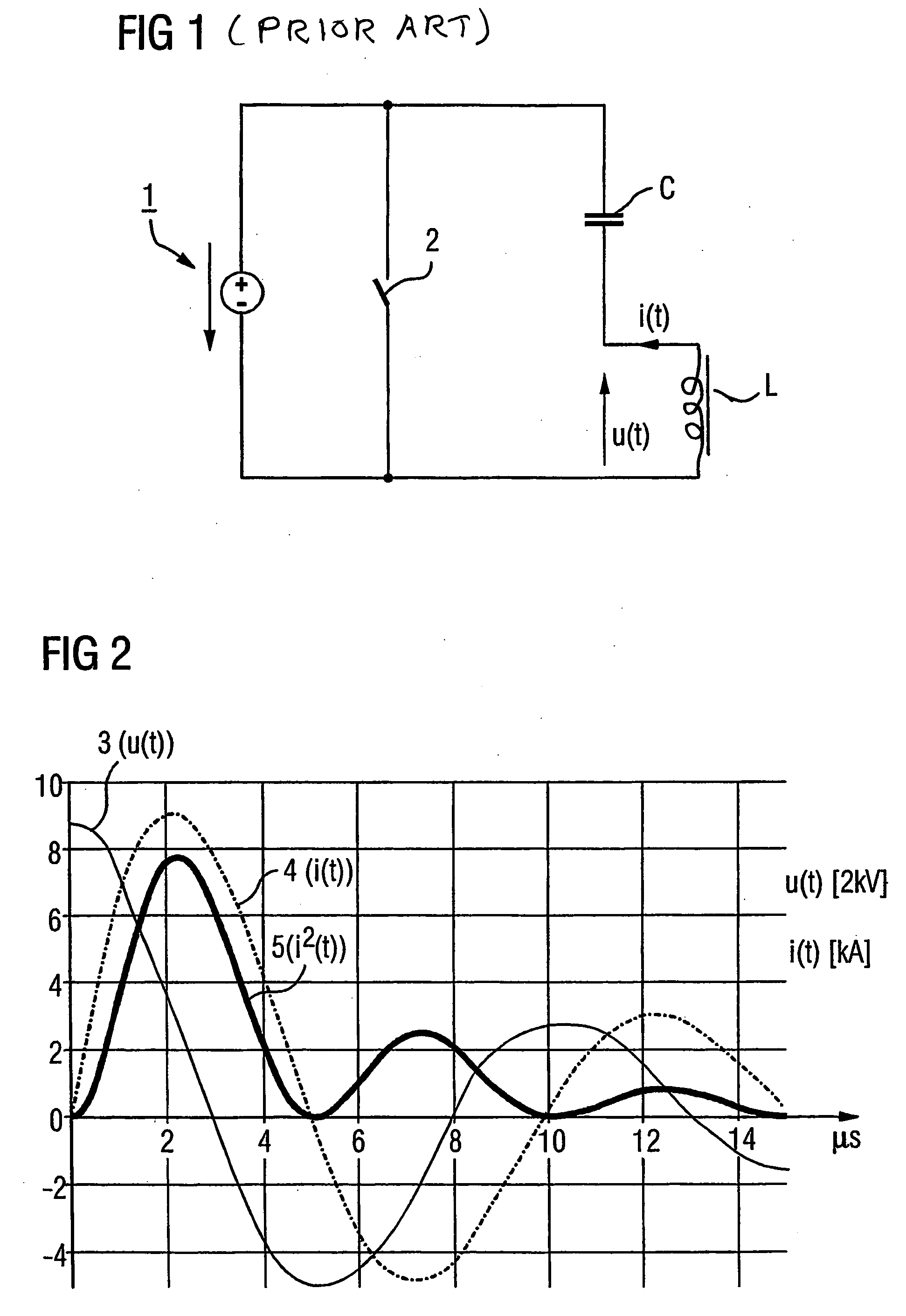
[0019] A temporal extension of the first source pressure pulse is achieved by the parallel connection of the second switching component to the capacitors given the discharge. Moreover, the subsequently decaying source pressure pulses dependent on the impedance of the second switching component are significantly damped. The damping can be so great that the subsequent source pressure pulses disappear entirely. Via the temporal extension of the first source pressure pulse, a stronger first acoustic wave (thus a stronger first shock wave) is generated, and an amplification of the volume results in an improved effect for the disintegration of calculi. Since only a few weak source pressure pulses, or even no source pressure pulses at all, occur subsequent to the first source pressure pulse, the tissue-damaging cavitation caused by shockwaves from the subsequent source pressure pulses and following the first shockwave is prevented. The lifespan of the first and the second capacitors is thereby increased by the conditionally reverse voltage reduced dependent on the second switching component. In addition, given such a generation of shock waves less audible sound waves are produced, so that a noise reduction results. The total area under the curve of the current is a determining factor in the generation of audible sound waves during the generation of shock waves. In the case of the present invention, this is reduced overall by the omission of the source pressure pulse normally following the first source pressure pulse.

Problems solved by technology

The shock waves directed at the kidney stone produce cracks in the kidney stone.
Due to the relatively high short circuit capacity up to the 100 MW range, a variable capacitance of the capacitor C and a variable inductance of coil L are costly.

Method used


Image

  • Switching circuit for an electromagnetic source for the generation of acoustic waves
  • Switching circuit for an electromagnetic source for the generation of acoustic waves
  • Switching circuit for an electromagnetic source for the generation of acoustic waves

Examples


Embodiment Construction

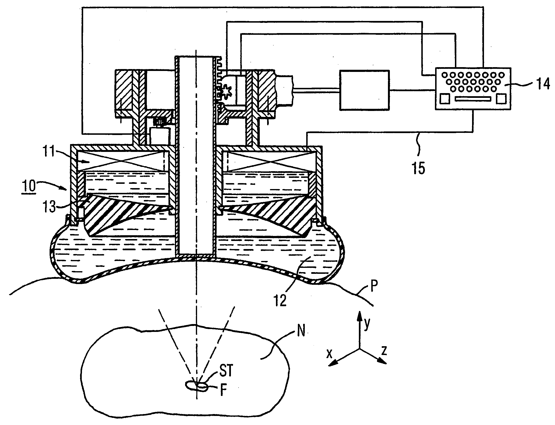
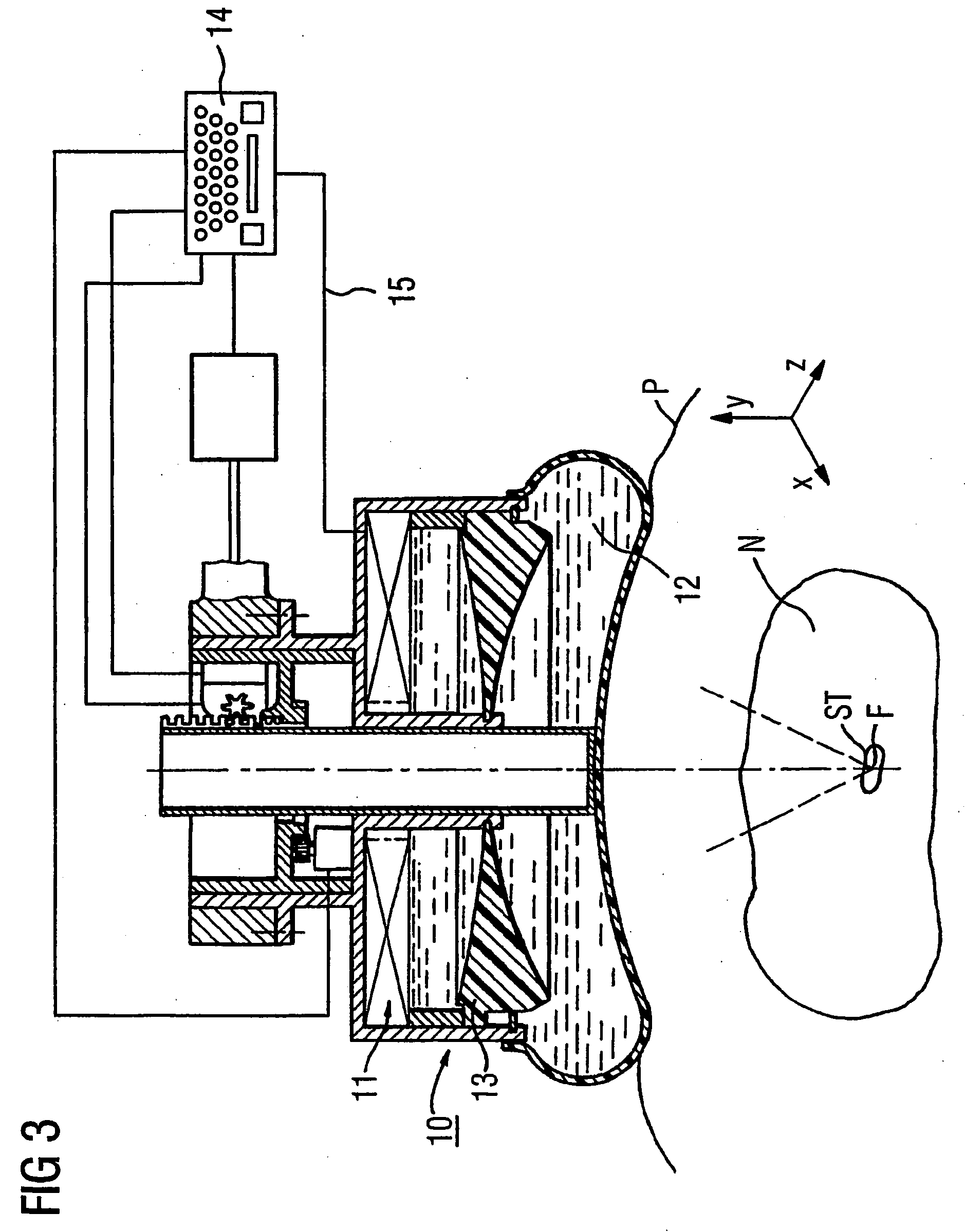
[0026] Partly in section and party in the form of a block diagram, FIG. 3 shows an electromagnetic shockwave source in the form of a therapy head 10 that, in the exemplary embodiment, is a component of a lithotripter (not shown in detail). The therapy head 10 has a known sound generation unit (designated with 11) that operates according to the electromagnetic principle. In FIG. 3, the sound generation unit 11 has (in a manner not shown) a coil carrier, a flat coil arranged thereon and a metallic membrane insulated from the flat coil. To generate shockwaves, the membrane is repelled in an acoustic propagation medium 12 by electromagnetic interaction with the flat coil, whereby a source pressure wave is emitted into the propagation medium. The source pressure wave of the acoustic lens 13 is focused on a focus zone F, whereby the source pressure wave is intensified into a shockwave during its propagation in the acoustic propagation medium 12 and after introduction into the body of a pa...


PUM


Abstract

A switching circuit for an electromagnetic source for generating acoustic waves has at least one first capacitor connected in parallel with a series circuit formed by a second capacitor and an electronic switch. The switching circuit is connected to a coil of the electromagnetic source, and the first and second capacitors are switched so as to both discharged into the coil, thereby supplying the coil with current.

Description

BACKGROUND OF THE INVENTION [0001] 1. Field of the Invention [0002] The present invention concerns a switching circuit for an electromagnetic source for the generation of acoustic waves of the type having a capacitor that is switched in parallel with at least one series circuit composed of another capacitor and a first diode. [0003] 2. Description of the Prior Art [0004] A switching circuit for an electromagnetic pressure wave source of the above type is known from German OS 198 14 331. It has two LC oscillators connected in series. Of these, the first switching circuit has a first capacitor and, in parallel to this, a semiconductor power switch formed by a triggerable thyristor and a recovery diode switched antiparallel to the thyristor, as well as a subsequent inductance. Part of this first switching circuit, switched in series with the semiconductor power switch and the inductance, as well as parallel to the first capacitor, is a second capacitor that likewise belongs to the seco...

Claims


Application Information

Patent Timeline
Patent Type & Authority Applications(United States)
IPC IPC(8): H01P1/10B06B1/02
CPCB06B1/0215B06B2201/53
Inventor ROHWEDDER, ARNIM
Owner SIEMENS AG
Why Eureka
Try Eureka