Fused array preform fabrication of holey optical fibers

a technology of optical fibers and preforms, applied in the direction of cladding optical fibers, manufacturing tools, instruments, etc., can solve the problems of inability to describe the optimal design of photonics, wavelength scattering and loss, and inability to allow light of other wavelengths, etc., to achieve the effect of reducing light scattering, reducing optical loss, and high quality

Inactive Publication Date: 2006-07-13
THE GOVERNMENT OF THE UNITED STATES OF AMERICA AS REPRESENTED BY THE SEC OF THE NAVY NAVAL RES LAB WASHINGTON
View PDF8 Cites 30 Cited by
  • Summary
  • Abstract
  • Description
  • Claims
  • Application Information

AI Technical Summary

Benefits of technology

[0015] Another object of this invention is the fabrication of high quality holey fibers characterized by transmission of l...

Problems solved by technology

This periodicity allows light of certain wavelengths to be conveyed through the fiber but will not allow light of other wavelengths, in the stop band, through.
These wavelengths will scatter and be lost.
It is not possible to describe an optimum design of photonic crystal fibers in general since different fibers are optimized for each of the above mentioned properties.
This is due primarily to the inability to fabricate holey fibers uniformly and reproducibly.
Although holey fibers are of great interest and the physics is quite well understood, experimental studies are hampered due to an inability to fabricate high quality fibers.
The greatest chall...

Method used


Image

  • Fused array preform fabrication of holey optical fibers
  • Fused array preform fabrication of holey optical fibers
  • Fused array preform fabrication of holey optical fibers

Examples


Embodiment Construction

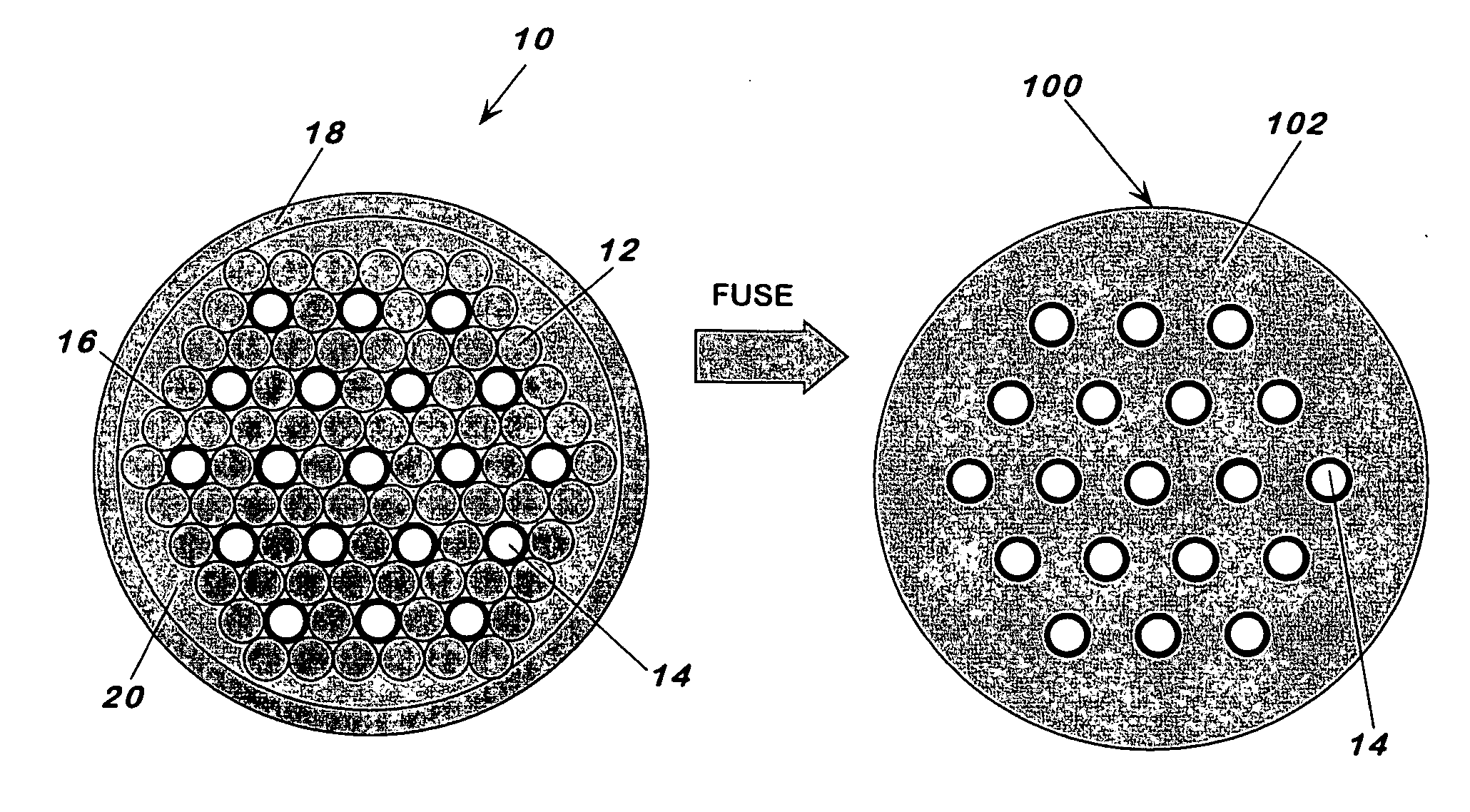
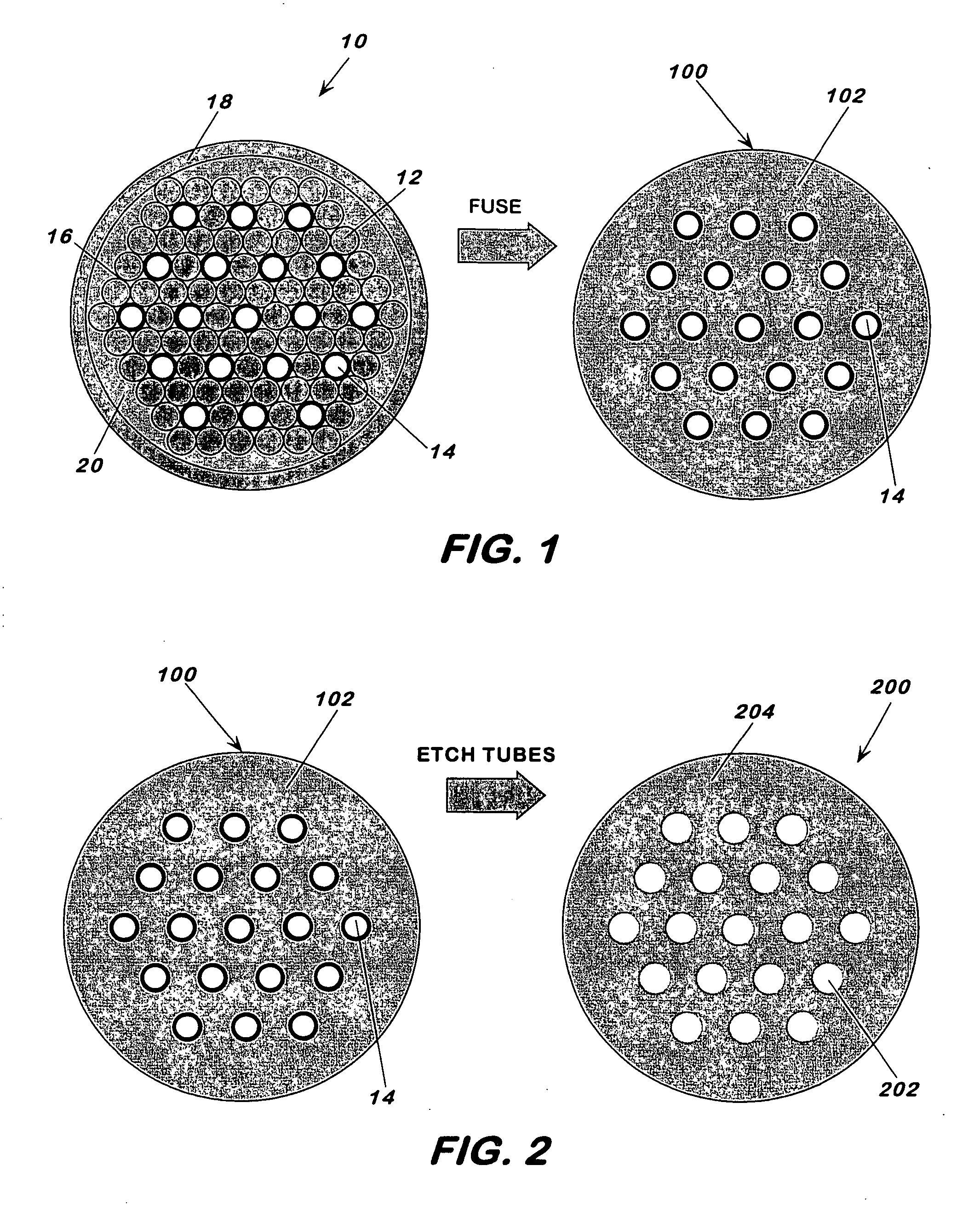
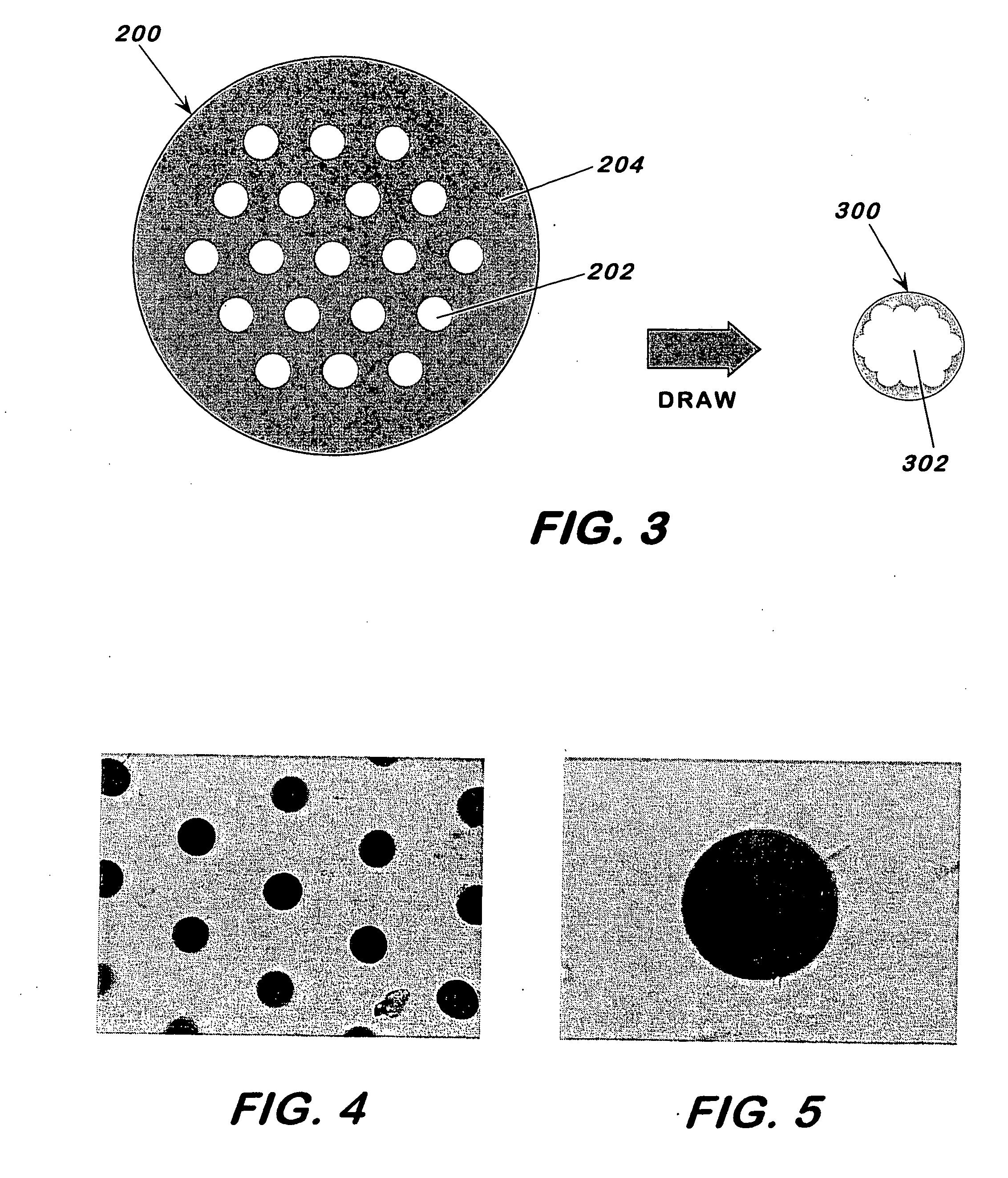
[0030] This invention pertains to a fabrication method for making holey fibers and to the holey fibers made thereby. The method generally includes the steps of stacking into a bundle rods and tubes in an arrangement, with the tubes having a softening point that is higher than that of the rods; heating the bundle to a temperature to fuse the rods but not the tubes and form a fused element characterized by a continuous phase around the tubes; removing the tubes to form a preform characterized by a continuous phase and channels, corresponding to the outline of the removed tubes, passing through the preform; and drawing the preform at a temperature below the softening temperature of the rods to form the holey fiber with solid or hollow core, having a periodic and highly uniform channel arrangement along the length of the fiber. For solid or hollow core holey fibers with or without photonic structure, no holes or holes of different sizes can be mixed and matched to obtain the desired eff...


PUM

PropertyMeasurementUnit
Fractionaaaaaaaaaa
Diameteraaaaaaaaaa
Diameteraaaaaaaaaa

Abstract

This invention pertains to a holey fiber and to a fabrication method for making the fiber. The holey fiber can transmit light by total internal reflection or by Bragg diffraction, can be single mode or multimode and can have solid core or a hollow core. The holey fiber has outside diameter typically of 20 microns to 5 mm, a hollow core of a diameter typically of 0.2 micron to 150 microns and longitudinal channels therethrough of a diameter typically of 0.1 micron to 150 microns. The channels are disposed in a desired arrangement with center-to-center distance variation of less than about 2% along the length of the fiber and the cross-section thereof is round that varies less than about 2%. The method includes the steps of stacking structures of at least two different materials of lower and higher softening points in a desired arrangement to form a bundle containing interstices between the structures; heating the bundle to a fusion temperature which is below the softening point of the higher softening point material to form a fused element whereby the lower softening point material softens and flows around the higher softening point material and closes the interstices; removing the structures of the higher softening point material from the fused element to form a preform, thus forming openings in the fused element; and drawing the preform at a draw temperature which is below the softening point of the lower softening point material to form the holey fiber.

Description

BACKGROUND [0001] 1. Field of the Invention [0002] This invention pertains to fabrication of optical holey fibers and to the optical holey fibers made thereby. [0003] 2. Description of Related Prior Art [0004] There is significant current interest in the novel optical properties of holey fibers. Holey fibers are typically glass fibers that are fabricated with a network of open channels or holes that run the length of the fiber. Theoretical and computational studies of the properties of holey fibers indicate that these fibers may be superior in many ways to conventional step index or gradient index solid glass fibers. All conventional optical fibers confine light by total internal reflection whereby light is confined within a core that has a higher index of refraction than the surrounding cladding. Holey fibers can confine light using either of two mechanisms: conventional total internal reflection or Bragg diffraction, which is also known as photonic band gap confinement. If light i...

Claims


Application Information

Patent Timeline
IPC IPC(8): G02B6/032C03B37/027C03B37/012G02B6/00G02B6/02
CPCC03B37/0122C03B37/02781C03B2203/14C03B2203/16C03B2203/22C03B2203/24C03B2203/42G02B6/02328G02B6/02347
Inventor FALKENSTEIN, PAUL L.JUSTUS, BRIAN
Owner THE GOVERNMENT OF THE UNITED STATES OF AMERICA AS REPRESENTED BY THE SEC OF THE NAVY NAVAL RES LAB WASHINGTON
Why Eureka
Try Eureka