
Fuel processor for use with portable fuel cells

a fuel processor and portable technology, applied in the field of fuel cell technology, can solve the problems that commercially available fuel cell systems are still restricted to large-scale applications, and achieve the effect of reducing the size of the fuel processor and facilitating the production of hydrogen

Inactive Publication Date: 2006-07-20
ULTRACELL ACQUISITION
View PDF99 Cites 40 Cited by
  • Summary
  • Abstract
  • Description
  • Claims
  • Application Information

AI Technical Summary

Benefits of technology

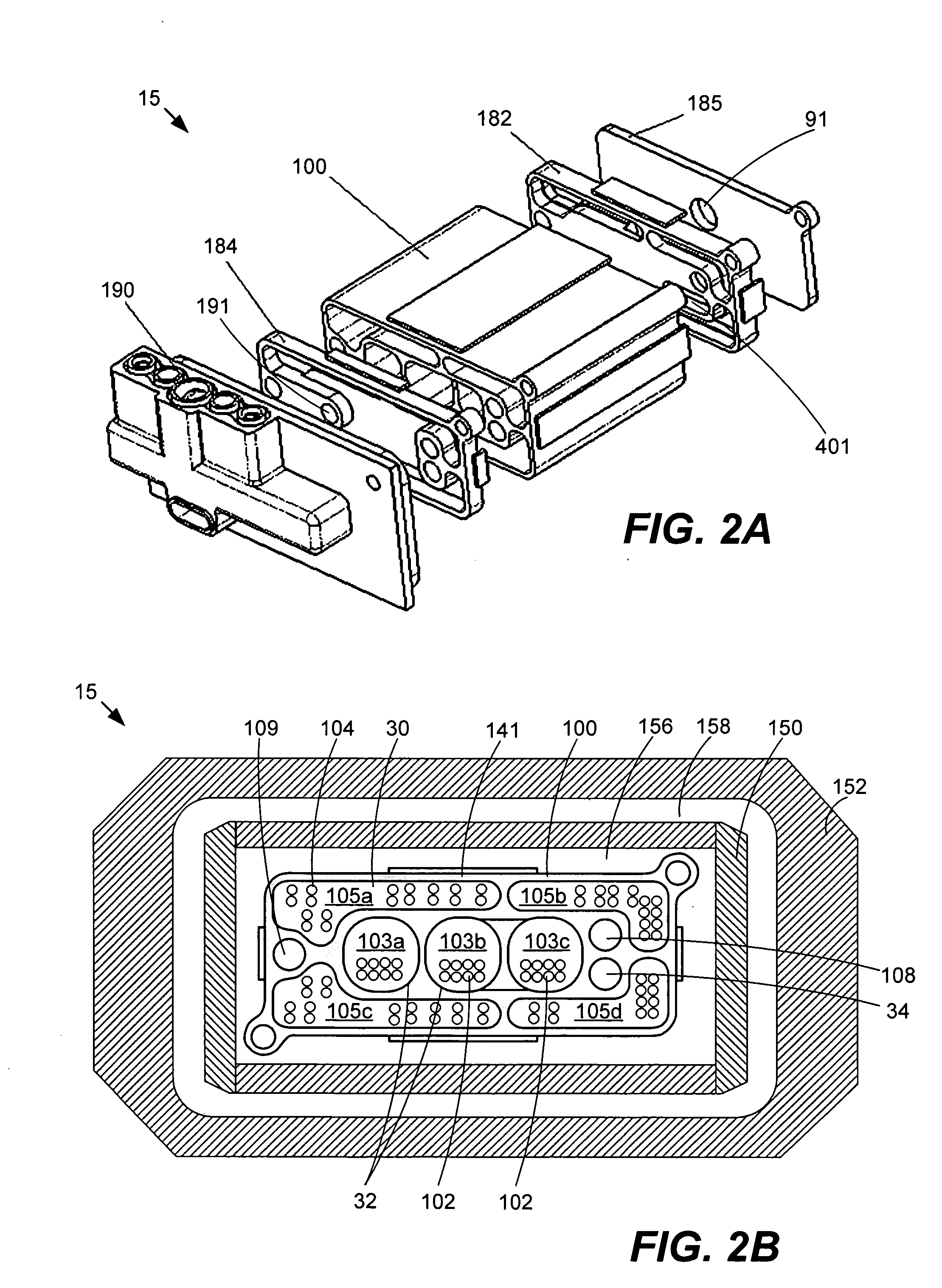
[0007] The present invention relates to a fuel processor that produces hydrogen from a fuel. The fuel processor includes a reformer and a heater. The reformer includes a catalyst that facilitates the production of hydrogen from the fuel; the heater provides heat to the endothermic reformer. Multipass reformer and heater chambers are described that reduce fuel processor size. Single layer fuel processors include reformer and heater chambers in a compact form factor that is well suited for portable applications.
[0010] In one aspect, the present invention relates to a fuel processor for producing hydrogen from a fuel. The fuel processor includes a reformer that includes a first reformer chamber and a second reformer chamber. The first reformer chamber includes: a first reformer chamber inlet configured to receive the fuel, a catalyst capable of processing the fuel to produce hydrogen, and a first reformer chamber outlet configured to output hydrogen and any unprocessed fuel from the first reformer chamber. The second reformer chamber includes: a second reformer chamber inlet configured to receive at least a portion of the fuel from the first reformer chamber, a catalyst capable of processing the portion of the fuel from the first reformer chamber to produce hydrogen, and a second reformer chamber outlet configured to output hydrogen from the second reformer chamber. The reformer is configured such that fuel can flow through the first reformer chamber from the first reformer chamber inlet to the first reformer chamber outlet in a first direction that is about parallel to a second direction that the fuel can flow through the second reformer chamber from the second reformer chamber inlet to the second reformer chamber outlet. The fuel processor also includes a heater configured to provide heat to the reformer. The fuel processor further includes a housing including a set of housing walls that provide external mechanical protection for the reformer and the heater.
[0011] In another aspect, the invention relates to an annular fuel processor. The fuel processor includes a burner, boiler, and reformer. The burner includes a burner fuel inlet configured to receive burner fuel and is configured to generate heat using the burner fuel. The boiler includes a boiler fuel inlet configured to receive reformer fuel, and a boiler chamber configured to receive heat from the burner and to heat the reformer fuel before the reformer receives the reformer fuel. The reformer is configured to receive the reformer fuel from the boiler, includes a catalyst that facilitates the production of hydrogen from the reformer fuel, and is configured to output hydrogen. The reformer is disposed relative to the burner in a cross section such that the reformer surrounds greater than 50 percent of a cross-sectional perimeter for the burner.

Problems solved by technology

Commercially available fuel cell systems are still restricted to large-scale applications, such as industrial size generators for electrical power back up.
Portable fuel cell systems and fuel processors for portable applications such as electronics offer extended usage sessions and would be desirable, but are not yet available.

Method used


Image

  • Fuel processor for use with portable fuel cells
  • Fuel processor for use with portable fuel cells
  • Fuel processor for use with portable fuel cells

Examples


Embodiment Construction

[0034] The present invention is described in detail with reference to a few preferred embodiments as illustrated in the accompanying drawings. In the following description, numerous specific details are set forth in order to provide a thorough understanding of the present invention. It will be apparent, however, to one skilled in the art, that the present invention may be practiced without some or all of these specific details. In other instances, well known process steps and / or structures have not been described in detail in order to not unnecessarily obscure the present invention.

Fuel Cell System

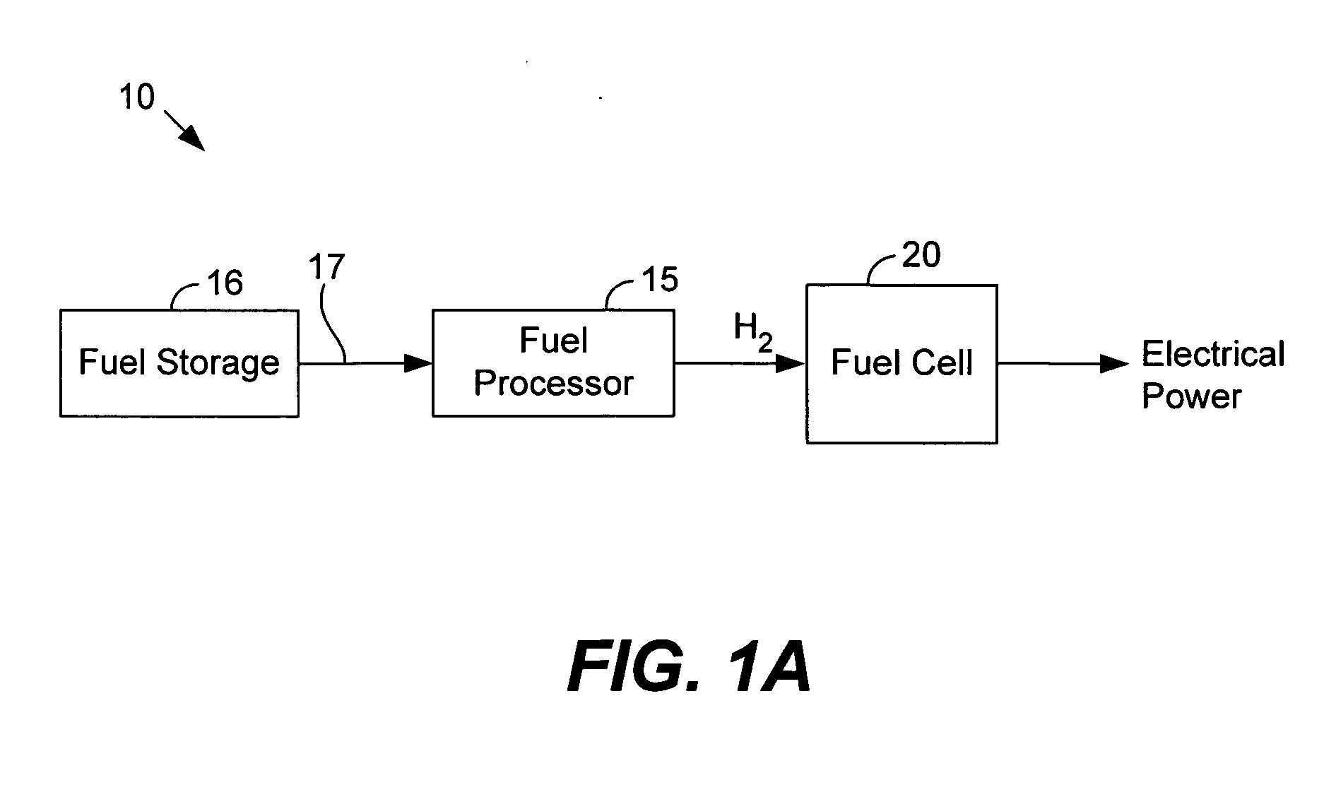
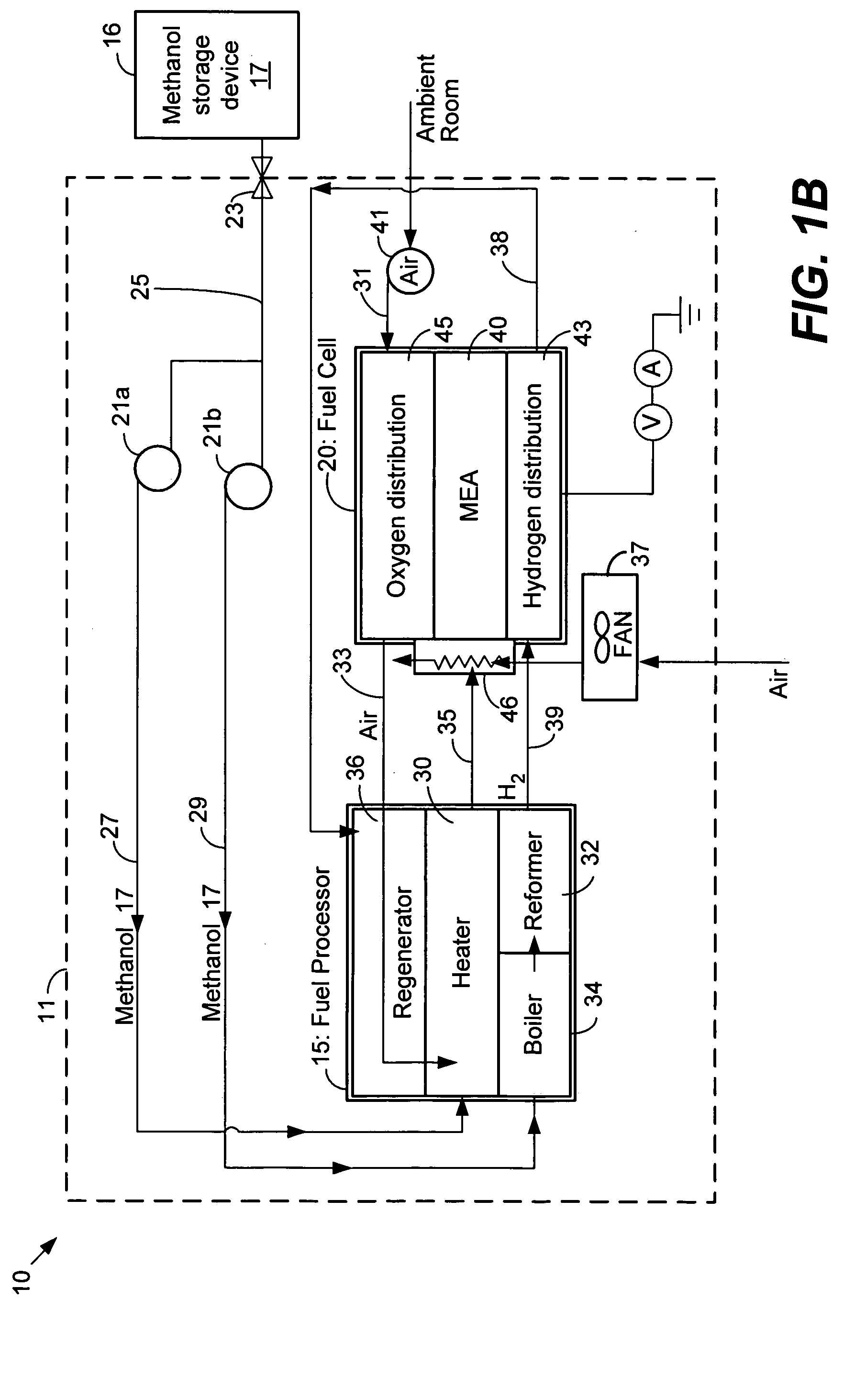
[0035] Before expanding upon fuel processors and components included therein, exemplary fuel cell systems will first be described. FIG. 1A illustrates a fuel cell system 10 for producing electrical energy in accordance with one embodiment of the present invention. The ‘reformed’ hydrogen system 10 processes a fuel 17 to produce hydrogen for supply to fuel cell 20. As shown, the reformed ...


PUM


Abstract

The invention relates to a fuel processor that produces hydrogen from a fuel. The fuel processor comprises a reformer and a heater. The reformer includes a catalyst that facilitates the production of hydrogen from the fuel; the heater provides heat to the reformer. Multipass reformer and heater chambers are described that reduce fuel processor size. Single layer fuel processors include reformer and heater chambers in a compact form factor that is well suited for portable applications. Some fuel processors described herein place an electrically resistive material in contact with a thermally conductive material to heat fuel entering the fuel processor. This is particularly useful during start-up of the fuel processor. Fuel processors described may also include features that facilitate assembly.

Description

CROSS-REFERENCE TO RELATED APPLICATIONS [0001] This application a) claims priority under 35 U.S.C. §120 to co-pending U.S. patent application Ser. No. 10 / 877,044, filed Jun. 25, 2004 and entitled, “ANNULAR FUEL PROCESSOR AND METHODS”, which claimed priority under 35 U.S.C. §19(e) from i) U.S. Provisional Patent Application No. 60 / 482,996 filed on Jun. 27, 2003, and ii) U.S. Provisional Patent Application No. 60 / 483,416 and filed on Jun. 27, 2003; [0002] and b) and claims priority under 35 U.S.C. §119(e) to: i) U.S. Provisional Patent Application No. 60 / 638,421 filed on Dec. 21, 2004 entitled “MICRO FUEL CELL ARCHITECTURE”, and ii) U.S. Provisional Patent Application No. 60 / 649,638 filed on Feb. 2, 2005 entitled “HEAT EFFICIENT MICRO FUEL CELL SYSTEM”; each of the patent applications listed above is incorporated by reference for all purposes.BACKGROUND OF THE INVENTION [0003] The present invention relates to fuel cell technology. In particular, the invention relates to fuel processor...

Claims


Application Information

Patent Timeline
IPC IPC(8): B01J7/00
CPCB01B1/005B01J8/0285B01J8/0496B01J12/007B01J15/005B01J19/2485B01J19/249B01J19/2495B01J2208/00203B01J2208/00309B01J2208/00504B01J2208/0053B01J2208/00672B01J2208/00716B01J2219/00157B01J2219/00159B01J2219/00783B01J2219/00788B01J2219/00804B01J2219/00822B01J2219/00824B01J2219/00828B01J2219/00835B01J2219/0086B01J2219/00862B01J2219/00869B01J2219/00871B01J2219/00873B01J2219/00997B01J2219/1923B01J2219/1943B01J2219/2453B01J2219/2458B01J2219/2459B01J2219/2462B01J2219/2465B01J2219/2479B01J2219/2481B01J2219/2485B01J2219/2493B01J2219/2497C01B3/323C01B3/38C01B3/382C01B3/384C01B2203/0227C01B2203/0233C01B2203/0244C01B2203/0261C01B2203/044C01B2203/047C01B2203/066C01B2203/0811C01B2203/0816C01B2203/0822C01B2203/0827C01B2203/0844C01B2203/085C01B2203/1223C01B2203/1229C01B2203/1241C01B2203/1247C01B2203/1288C01B2203/142C01B2203/169C01B2203/82H01M8/04022H01M8/0618H01M8/0631H01M8/0662H01M2008/1095Y02E60/50Y02P20/10
Inventor BRANTLEY, JENNIFER E.KAYE, IAN W.SOMOGYVARI, ARPADTUCKER, GERRYCHAN, FAN LIANG
Owner ULTRACELL ACQUISITION
Learn More