
Drive rod structure of a tool lock device

a technology of tool lock and drive rod, which is applied in the direction of screwdrivers, wrenches, belts/chains/gearings, etc., can solve the problems of increased manufacturing difficulty and cost, increased quantity of forging molds, and falling off, so as to improve manufacturing efficiency and reduce manufacturing difficulty and cost , the effect of reducing the number of forging molds

Inactive Publication Date: 2006-07-20
CHU CHING TSENG +1
View PDF4 Cites 0 Cited by
  • Summary
  • Abstract
  • Description
  • Claims
  • Application Information

AI Technical Summary

Benefits of technology

[0010] The primary purpose of the present invention is to substantially reduce the manufacturing cost and increase the usage life of a tool lock device.
[0014] According to the process, the drive rod manufacturing is simplified effectively while its structure strength is reinforced, and further reaches the features of easy to be fabricated, firmed structure strength and everlasting color to enhance the economic benefits.

Problems solved by technology

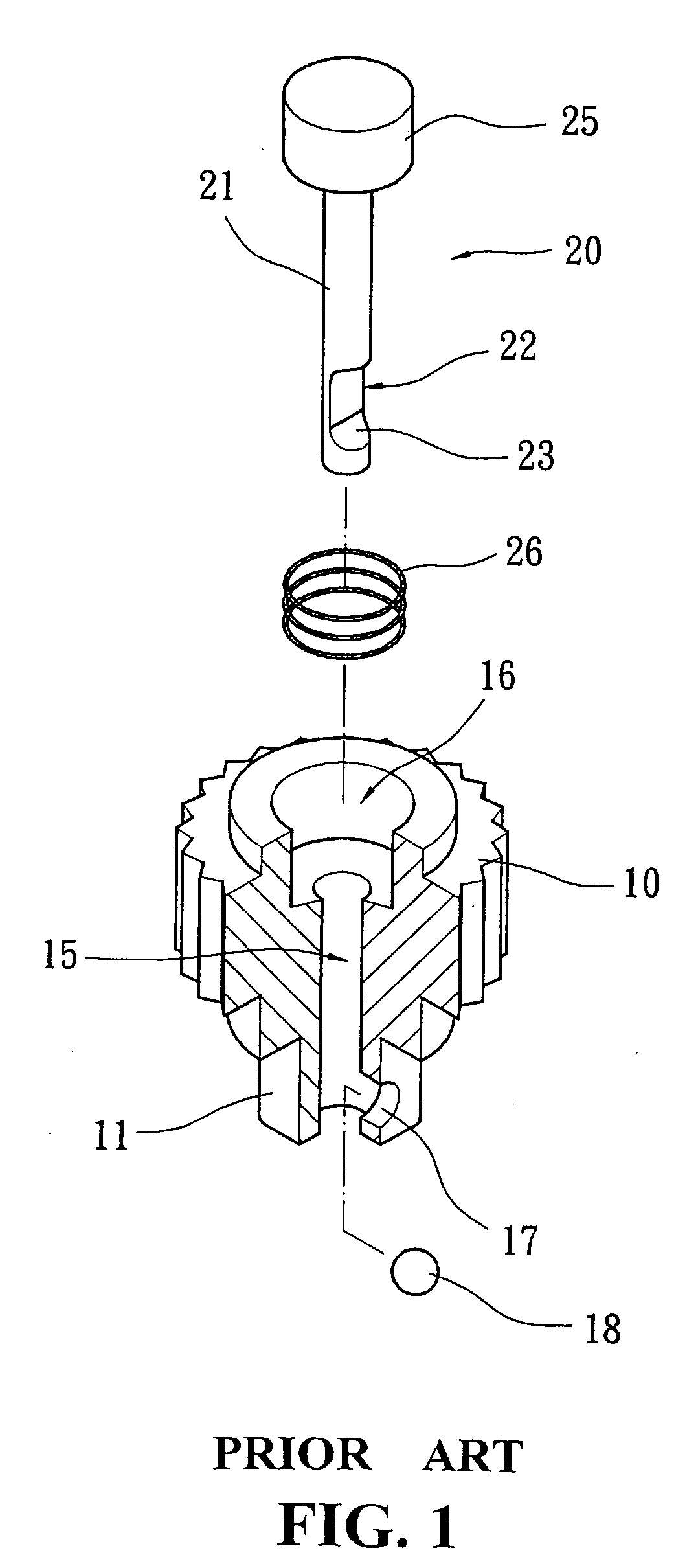
However, when the diameter differences between the rod body 21 of the drive rod 20 and the push head 25 of the drive rod 20 are large, the quantity of the forging mold will increase, which will simultaneously increase the manufacturing difficulty and cost.
The colors, however, easily come off by accident hit and lack variety, which will lose the economic benefits.
Because its plastic body does not have enough hardness and the contact area is too small.
As previously described, the present drive rod structures have different problems no matter they are made of metal or plastic.

Method used


Image

  • Drive rod structure of a tool lock device
  • Drive rod structure of a tool lock device
  • Drive rod structure of a tool lock device

Examples


Embodiment Construction

[0022] The following descriptions are of exemplary embodiments only, and are not intended to limit the scope, applicability or configuration of the invention in any way. Rather, the following description provides a convenient illustration for implementing exemplary embodiments of the invention. Various changes to the described embodiments may be made in the function and arrangement of the elements described without departing from the scope of the invention as set forth in the appended claims.

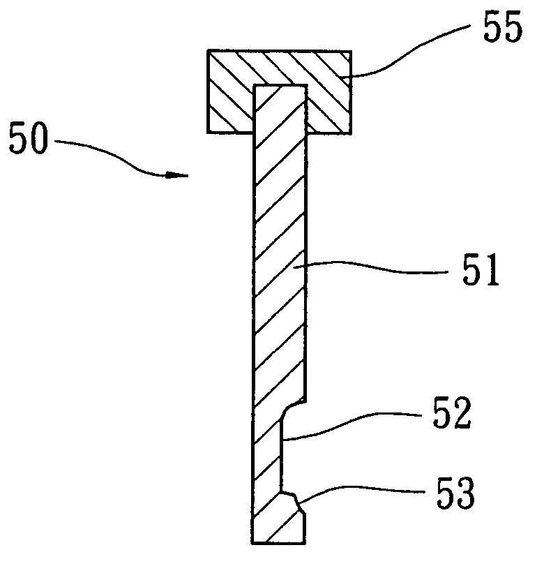
[0023] The present invention relates to a drive rod structure of a lock device which is easy to be fabricated, with firmed structure strength and with everlasting color, as shown in FIGS. 4 and 5. The drive rod 50 primarily comprises a metal rod body 51 and a plastic push head 55.

[0024] Still referring to FIGS. 4 and 5, the detailed structure of the present invention comprises the rod body 51 made of metallic material, where iron rod is illustrated in the embodiment. The iron rod is first fabr...


PUM


Abstract

The present invention relates to a drive rod structure of a tool lock device, and more particularly, to a drive rod with the features of easy to be fabricated, finned structure strength and everlasting color. The drive rod comprises a metal rod body and a push head, where the mental rod body is pre-manufactured with a ball-containing groove and an arc-concaved guide edge at one end, and then the opposite end of the rod body is disposed in the push head mold with plastic push head material. The drive rod is formed by one-shot plastic injection combining the plastic push head and the metal rod body. Thus, it can solve the present drive rod problems, which are not easy to be fabricated and have weak structure strength, and reach the features of easy to be fabricated, firmed structure strength and everlasting color. Eventually, the present invention cannot only increase the convenience of the manufacturing and the economic benefits, but only prolong the usage life effectively.

Description

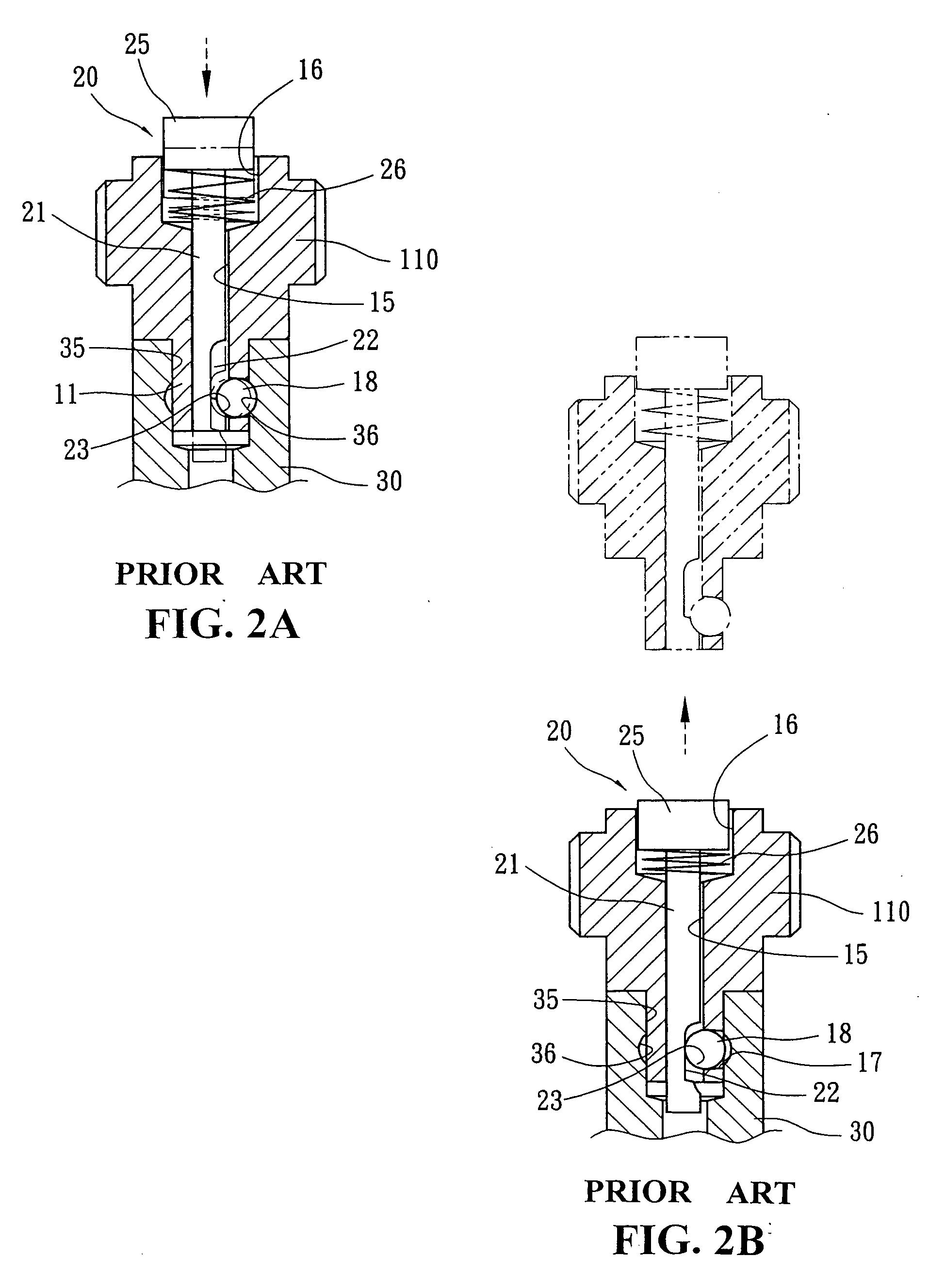
BACKGROUND OF INVENTION [0001] (a) Technical Field of the Invention [0002] The present invention relates to a drive rod of a tool lock device which functions as a clutch device, and more particularly, to a special design for combining a mental rod body and a plastic push head which will increase variety of the push head and strength of the rod body to reach the purpose of easy-to-fabricate and prolonging the usage life of the drive rod. [0003] (b) Description of the Prior Art [0004] In general, when a tool set needs the function to connect or release its parts, it usually needs a lock device. As shown in FIGS. 1 and 2, a lock device of a ratchet wrench comprises a multi-angle lock rod 11 extending from one end of a ratchet wheel 10 which provides the combination to a corresponding sink hole 35 of a tool head 30, a through hole 15 formed and extending axially in the middle of the ratchet wheel which has a sink hole 17 corresponding to one side of the lock rod 11 for a positioning ste...

Claims


Application Information

Patent Timeline
Patent Type & Authority Applications(United States)
IPC IPC(8): F16H57/00
CPCY10T74/19605B25B23/0035
Inventor CHU, CHING-TSENGHSU, CHZN-SUNG
Owner CHU CHING TSENG
Learn More