Cooling device of thin plate type for preventing dry-out

a cooling device and thin plate technology, applied in semiconductor/solid-state device details, lighting and heating apparatus, laminated elements, etc., can solve the problems of deteriorating the performance of semiconductor devices, reducing life expectancy, and increasing the heat emission rate of semiconductor devices per unit area, so as to improve the flow of coolant and improve the cooling efficiency

Inactive Publication Date: 2006-07-20
ICURIE LAB HLDG
View PDF7 Cites 71 Cited by
  • Summary
  • Abstract
  • Description
  • Claims
  • Application Information

AI Technical Summary

Benefits of technology

[0011] Moreover, it is another object of the present invention to provide a thin plate-type cooling device wherein its cooling efficiency is increased by improving the flow of the coolant.

Problems solved by technology

As design rules decrease due to the trend towards large scale integration of semiconductor devices, and thereby the line width of electronic devices constituting semiconductor devices narrows, small-sized and high performance electronic equipment has been achieved owing to a larger number of transistors per unit area, which causes, however, that the ratio of heat emission of a semiconductor device per unit area increases.
The increase of the rate of heat emission deteriorates the performance of semiconductor devices and lessens the life expectancy thereof, and eventually decreases the reliability of a system adopting semiconductor devices.
Particularly in semiconductor devices, parameters are too easily affected by operation temperatures, and thereby it further deteriorates the characteristics of integrated circuits.
The fin-fan type cooler which compulsorily cools devices using fins and / or fans has been used for tens of years, but has some defects such as noise, vibration, and low cooling efficiency as compared with its large volume.
Although the peltier type cooler doesn't make noise or vibration, it has a problem that it requires too many heat dissipation devices at its hot junction, needing large driving power due to its low efficiency.
The water-jet type cooler goes mainstream in cooling device research because of its excellent efficiency, but its structure is complicated due to the use of a thin film pump driven by an external power supply, and it is significantly affected by gravity, as well as a problem that it is difficult to achieve robust design when applied to personal mobile electronic equipment.
And there is a problem that its installation location is significantly restricted because the coolant gasified inside the pipe moves depending upon buoyancy and pressure difference, and the liquefied coolant in the heat pipe depends on gravity due to the structure and size of the medium of the returning section.
According to the thin plate-type cooling device disclosed, however, there is a possibility that the coolant in the gas state is not completely condensed in the condensation section and reaches the condensation section via the liquefied coolant transfer section and / or the coolant storage section, contained in the condensed coolant in the form of bubbles.
If the bubbles contained in the coolant in the liquid state reach the evaporation section, there is concern that the dry-out phenomenon by which the coolant in the liquid state is exhausted occurs in the evaporation section.

Method used


Image

  • Cooling device of thin plate type for preventing dry-out
  • Cooling device of thin plate type for preventing dry-out
  • Cooling device of thin plate type for preventing dry-out

Examples


first embodiment

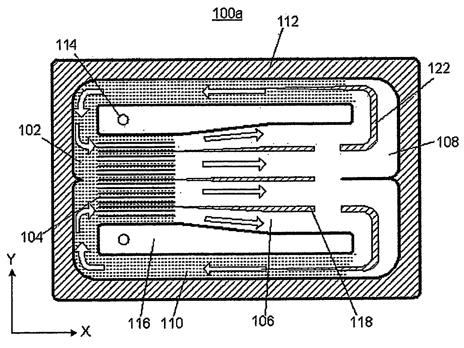
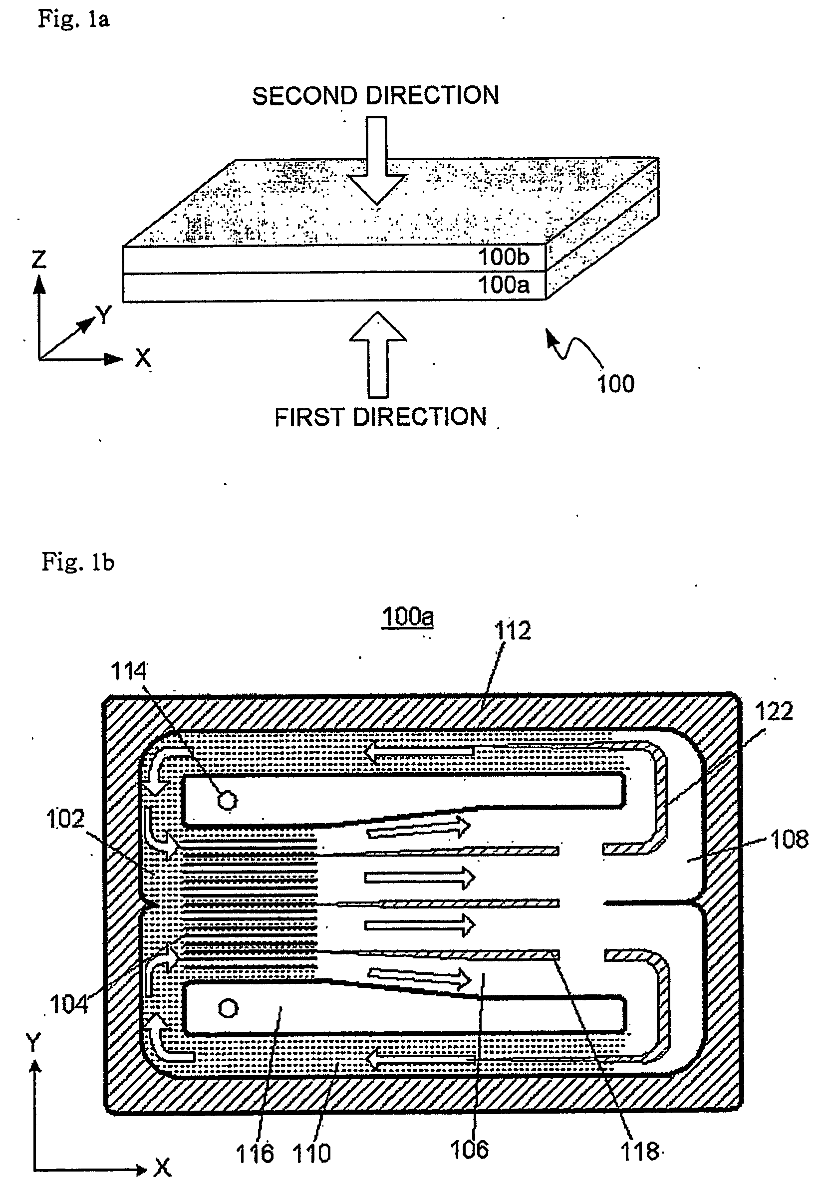
[0029] Referring to FIG. 1a, first, FIG. 1a shows the external appearance of a thin plate-type cooling device 100 according to this invention. It is preferable that the external appearance of the thin plate-type cooling device 100 of this invention is approximately rectangular, and the thin plate-type cooling device 100 is formed by bonding a lower plate 100a and an upper plate 100b in each of which internal elements have been formed.

[0030] For the sake of understanding and description, it is defined that, as shown in FIG. 1a, an “X-axis direction” is the longitudinal direction (from the left to the right of the drawing) of the thin plate-type cooling device 100 of this invention, a “Y-axis direction” is the lateral direction (into the drawing) of the thin plate-type cooling device 100, and a “Z-axis direction” is the vertical direction (from the bottom of the top of the drawing) of the thin plate-type cooling device 100. Moreover, it is also defined that a “section viewed in a firs...

third embodiment

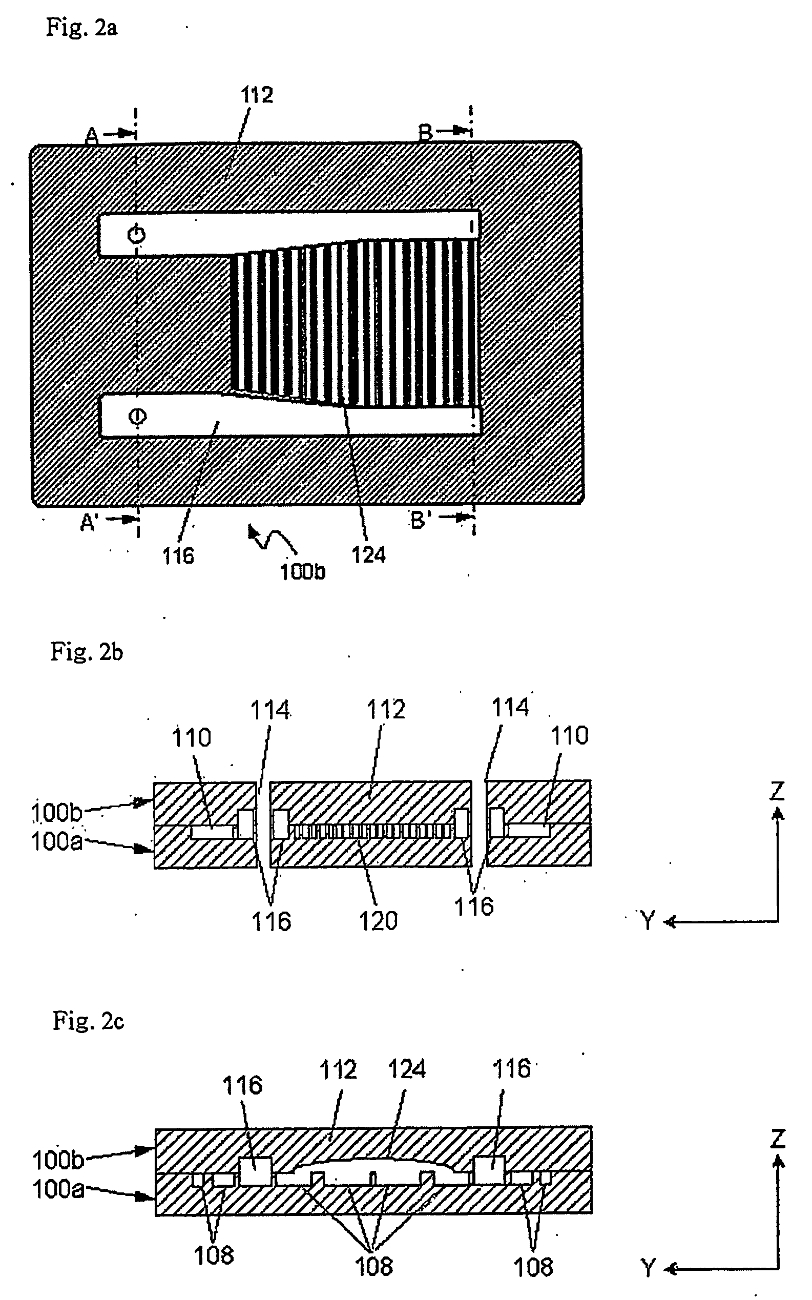
[0064] As shown in the drawings, the upper plate 100b of the thin plate-type cooling device 100 in the third embodiment further includes a plurality of second cavities 126 formed on areas corresponding to the condensation section 108 of the lower plate 100a. That is, the upper plate 100b includes the plurality of the first cavities 124 formed on areas corresponding to the gaseous coolant transfer section 106 of the lower plate 100a and the plurality of second cavities 126 formed on areas corresponding to the condensation section 108 of the lower plate 100a, where the first and second cavities 124 and 126 are respectively connected to each other.

[0065] Moreover, as shown in the drawing, it is preferable that the width of each of the second cavities 126 becomes narrow as it proceeds to the area corresponding to the liquefied coolant transfer section 110. Accordingly, when the lower plate 100a and the upper plate 100b are bound, the sections of the second cavities 126 become small as t...


PUM

PropertyMeasurementUnit
surface tensionaaaaaaaaaa
phase transitionaaaaaaaaaa
temperaturesaaaaaaaaaa

Abstract

The present invention provides a thin plate type cooling device including at least one cavity formed on an inside wall of coolant circulation loop in order to prevent dry-out of the coolant.

Description

TECHNICAL FIELD [0001] The present invention relates to a thin plate-type cooling device for cooling a semiconductor integrated circuit device, etc., and more particularly to a thin plate-type cooling device capable of preventing a coolant from drying out using the phase transition of operation fluid. BACKGROUND ART [0002] As design rules decrease due to the trend towards large scale integration of semiconductor devices, and thereby the line width of electronic devices constituting semiconductor devices narrows, small-sized and high performance electronic equipment has been achieved owing to a larger number of transistors per unit area, which causes, however, that the ratio of heat emission of a semiconductor device per unit area increases. The increase of the rate of heat emission deteriorates the performance of semiconductor devices and lessens the life expectancy thereof, and eventually decreases the reliability of a system adopting semiconductor devices. Particularly in semicond...

Claims


Application Information

Patent Timeline
Patent Type & Authority Applications(United States)
IPC IPC(8): F28D15/00F28D15/02F28F3/12H01L23/427H01L23/473
CPCB82Y30/00F25B2339/021F28D15/0233F28D15/0266F28F3/12F28F2245/02F28F2245/04H01L2924/0002H01L23/427H01L23/473H01L2924/3011F28F2270/00H01L2924/00F28D15/02
Inventor CHOI, JAE JOONPARK, JIHWANGLEE, JEONG HYUNLEE, CHANG HO
Owner ICURIE LAB HLDG
Why Eureka
Try Eureka