Method and apparatus for forming surface, magnetic head and method of manufacturing the same

a technology of magnetic head and surface forming apparatus, which is applied in the direction of recording head housing/shield, recording information storage, instruments, etc., can solve the problems of unfavorable surface forming processing on the bar block b, and the inability to thoroughly investigate the mechanical distortion generated in the bar block

Inactive Publication Date: 2006-07-20
SAE MAGNETICS (HK) LTD
View PDF6 Cites 4 Cited by
  • Summary
  • Abstract
  • Description
  • Claims
  • Application Information

AI Technical Summary

Benefits of technology

[0033] The present invention is formed and functions as described above. In the present invention, the surface forming process is performed by irradiating the energy beam without performing the mechanical surface forming process. Thus, it is possible to manufacture the structural body having no quality changes due to the mechanical process, which is an excellent effect that is not of the conventional case. Furthermore, shielding the irradiation of the energy beam to the individual structural bodies provides the proper surface forming process to the individual structural bodies. Therefore, it can achieve such an excellent effect that all the structural bodies can be polished uniformly with high quality, which is not of the conventional case.

Problems solved by technology

Therefore, conventionally, there has not been thoroughly investigated to deal with mechanical distortion that is generated in the bar block, i.e. inside the magnetic head structure, which is caused by the mechanical polishing and to deal with changes and deterioration of the property of the magnetoresistive element.
Furthermore, there may be a small margin in the height or the like of each magnetoresistive element M included in the individual magnetic head structure R within the bar block B generated at the time of laminating the thin films or cutting the wafer into the bar blocks B. Moreover, the surface forming processing on the bar block B may not be performed uniformly.

Method used


Image

  • Method and apparatus for forming surface, magnetic head and method of manufacturing the same
  • Method and apparatus for forming surface, magnetic head and method of manufacturing the same
  • Method and apparatus for forming surface, magnetic head and method of manufacturing the same

Examples


first embodiment

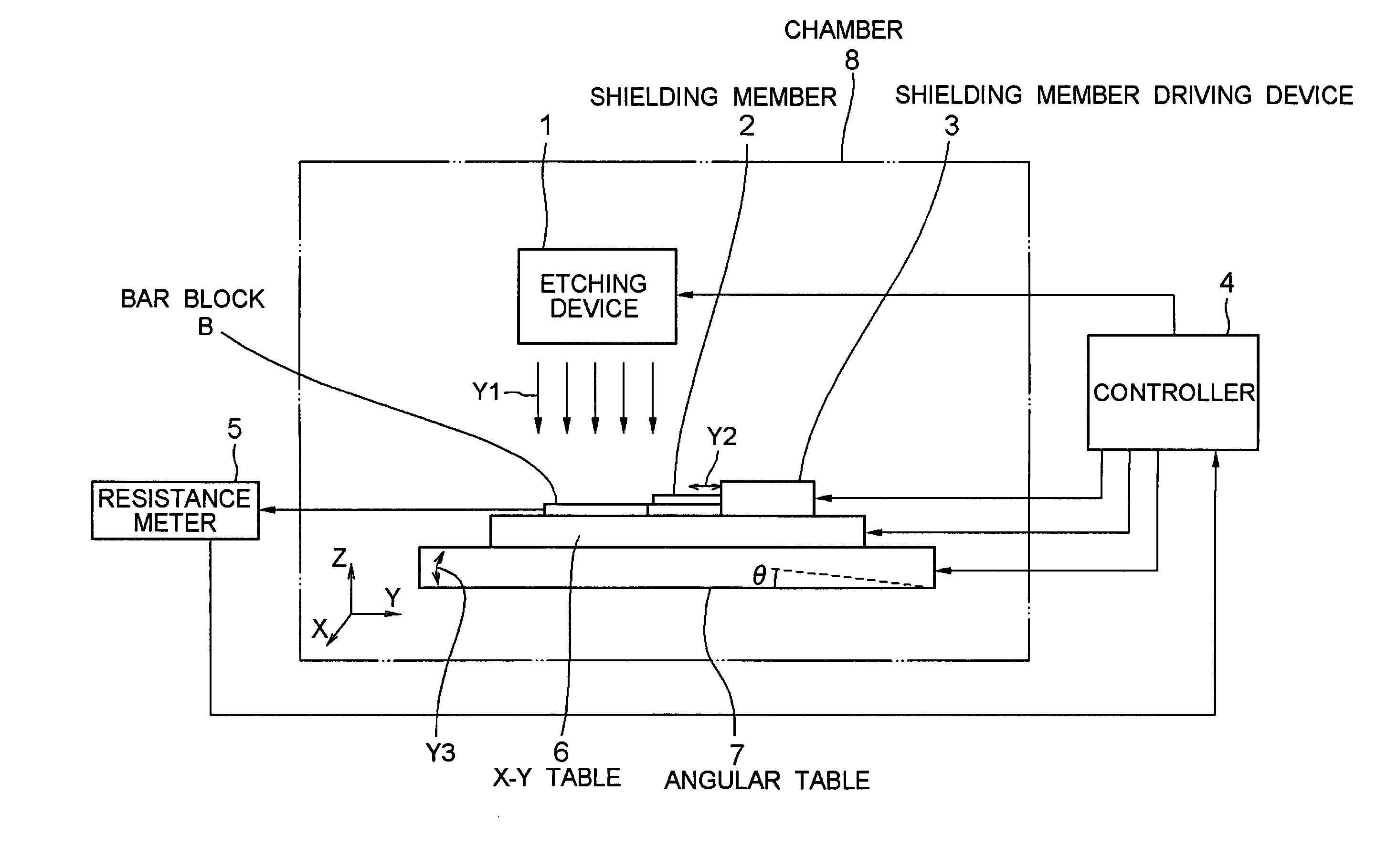
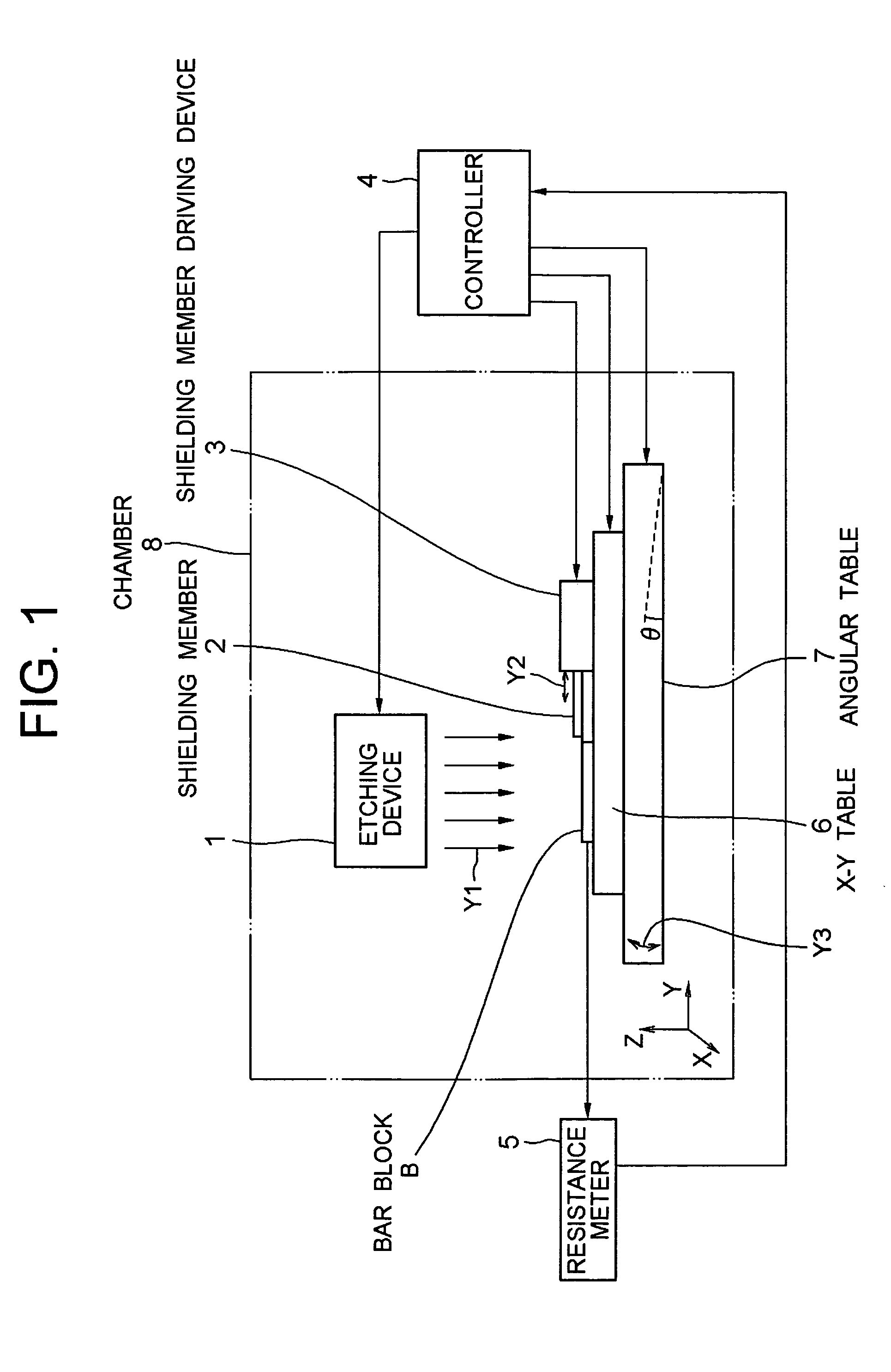
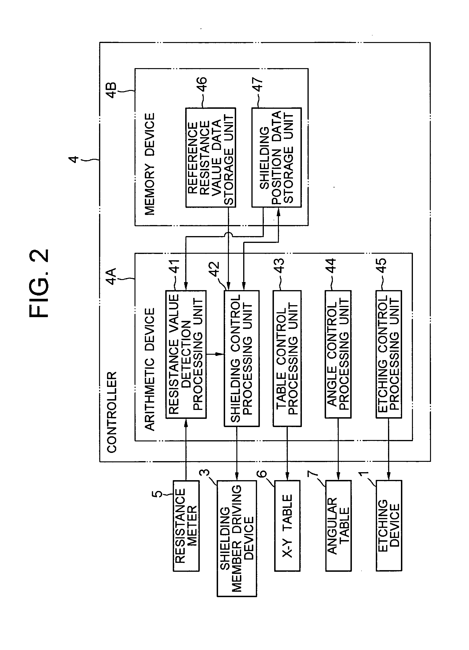
[0044] A first embodiment of the present invention will be described by referring to FIG. 1-FIG. 5. FIG. 1 is a block diagram for showing the structure of the surface forming apparatus. FIG. 2 is a functional block diagram for showing the structure of a controller. FIG. 3 and FIG. 4 are illustrations for describing the state of the magnetic head at the time of surface forming process. FIG. 5 is a flowchart for showing the surface processing action.

[Structure]

[0045] As shown in FIG. 8 and described as the related art, the surface forming apparatus according to the present invention is an apparatus that performs surface forming processing, e.g. etching an air bearing surface on a bar-type block (bar block B) in which magnetic heads R are arranged in line, i.e. a wafer W including a plurality of magnetic heads R. Thus, the surface forming apparatus constitutes a part of a magnetic head manufacturing apparatus.

[0046] As shown in FIG. 1, the surface forming apparatus according to the ...

second embodiment

[0081] Next, a second embodiment of the present invention will be described by referring to FIG. 6 and FIG. 7. FIG. 6 is a functional block diagram for showing the structure of a controller of a surface forming apparatus according to the embodiment. FIG. 7 is a flowchart for showing the action of the surface forming apparatus according to the embodiment.

[0082] Basically, the surface forming apparatus of the embodiment employs almost the same structure as that of the surface forming apparatus described in the first embodiment. However, it is different in terms of the structure for judging the timing of shielding the energy beams by driving the shielding member 2. That is, in the above-described first embodiment, shielding is performed based on the resistance value of the magnetoresistive element M of the magnetic head R. However, in this embodiment, the element height Mh of the magnetoresistive element M is detected and the shielding action is controlled in accordance with the chang...

third embodiment

[0093] Next, a third embodiment of the present invention will be described. The embodiment is distinctive in respect that the above-described timing of shielding is judged based on both the resistance value of the magnetoresistive element M and the irradiation time of the ion beams. In other words, the shielding action is controlled in accordance with the changes in the property of the magentoresistive element M and the element height Mh of the magnetoresistive element M during etching.

[0094] For example, as in the above-described first embodiment, the surface forming apparatus of the third embodiment detects the resistance value and compares it to the reference resistance value, and detects the irradiation time of the ion beams as well to compare it to the reference irradiation time. When a prescribed condition is satisfied, e.g. when either one is within the range of respective reference value or the both detected values are within the ranges of the respective reference values, t...


PUM

PropertyMeasurementUnit
heightaaaaaaaaaa
energyaaaaaaaaaa
heightaaaaaaaaaa

Abstract

It is to manufacture uniform and high-quality structural bodies which face no quality changes due to mechanical process. There is provided a surface forming apparatus that comprises a surface forming device for performing surface forming process to a prescribed structural body, wherein the surface forming device is an irradiation device that irradiates, to the structural body, an energy beam with a prescribed irradiation energy, which can be irradiated in a specific direction.

Description

BACKGROUND OF THE INVENTION [0001] 1. Field of the Invention [0002] The present invention relates to a method and an apparatus for forming a surface and, particularly, to a method and an apparatus for forming a surface, which perform surface forming process without applying mechanical polishing. Further, the present invention relates to a structural body and a magnetic head manufactured by performing the surface forming process and to a manufacturing method of the same. [0003] 2. Description of the Related Art [0004] Recently, there has been an remarkable improvement in the recording density of a hard disk drive (referred to as “HDD” hereinafter), and a magnetoresistive element is used as a magnetic head for reproducing data from the magnetic disk with high recording density. For example, there is a magnetic head part using a giant magnetoresistive element (GMR element) or a tunnel junction magnetoresistive element (TMR element) as the magnetoresistive element. [0005] In general, th...

Claims


Application Information

Patent Timeline
Patent Type & Authority Applications(United States)
IPC IPC(8): B44C1/22H01L21/306
CPCG11B5/102G11B5/3163G11B5/3166G11B5/3173G11B5/6011
Inventor ITO, YOSHIAKINAKADA, TAKESHIUEDA, KUNIHIROYAMAGUCHI, MASAO
Owner SAE MAGNETICS (HK) LTD
Why Eureka
Try Eureka