
Imaging apparatus and imaging method

a technology of image sensor and image sensor, which is applied in the field of imaging apparatus and imaging method using solid-state image sensor, can solve problems such as degrading the quality of the capture image, and achieve the effect of improving the quality of the image captured by the solid-state image sensor adopting the xy address method

Inactive Publication Date: 2006-07-20
THOMSON LICENSING SA
View PDF6 Cites 147 Cited by
  • Summary
  • Abstract
  • Description
  • Claims
  • Application Information

AI Technical Summary

Benefits of technology

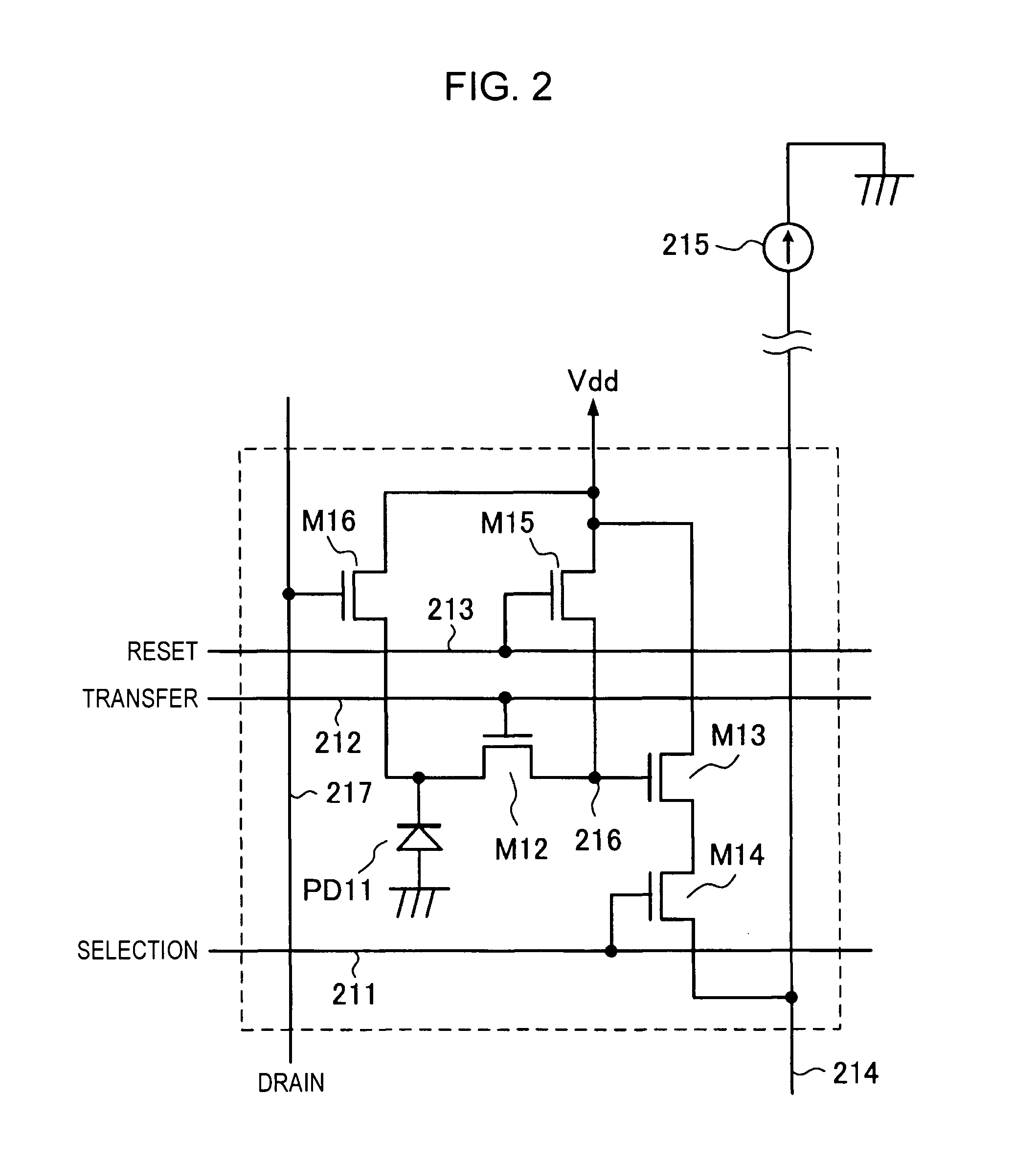
[0029] In addition, when the signal charge is held in the FD, as in the CMOS image sensor shown in FIG. 2, dark current has a greater effect on the CMOS image sensor, compared with the case in which the signal charge is held in the photodiode, to increase dark noise and to degrade the image quality.
[0031] It is desirable to provide an imaging apparatus configured to prevent distortion in an image captured by a solid-state image sensor adopting the XY address method and to suppress the amount of noise caused by light filtering into the pixel circuit.
[0032] It is also desirable to provide an imaging method capable of preventing distortion in an image captured by a solid-state image sensor adopting the XY address method and of suppressing the amount of noise caused by light filtering into the pixel circuit.
[0034] In such an imaging apparatus, simultaneously resetting the pixel signals of the solid-state image sensor for all the rows to start the exposure to the solid-state image sensor and, then, closing the mechanical shutter synchronize the exposure periods for all the rows. In addition, sequentially reading out the pixel signals of the solid-state image sensor for every row with the mechanical shutter being closed avoids a phenomenon in which light filters into the circuit in the solid-state image sensor.
[0036] With such an imaging method, simultaneously resetting the pixel signals of the solid-state image sensor for all the rows to start the exposure to the solid-state image sensor in the exposure starting step and, then, closing the mechanical shutter in the exposure terminating step synchronize the exposure periods for all the rows. In addition, in the exposure terminating step, sequentially reading out the pixel signals of the solid-state image sensor for every row with the mechanical shutter being closed avoids a phenomenon in which light filters into the circuit in the solid-state image sensor.
[0037] According to the present invention, since the pixel signals of the solid-state image sensor are simultaneously reset for all the rows to start the exposure to the solid-state image sensor and, then, the mechanical shutter is closed in order to synchronize the exposure periods for all the rows, no distortion occurs in the captured image. In addition, since the pixel signals of the solid-state image sensor are sequentially read out for every row with the mechanical shutter being closed to avoid a phenomenon in which light filters into the circuit in the solid-state image sensor, noise due to the filtering light is not produced in the captured image. Accordingly, the quality of the image captured by the solid-state image sensor adopting the XY address method can be improved.

Problems solved by technology

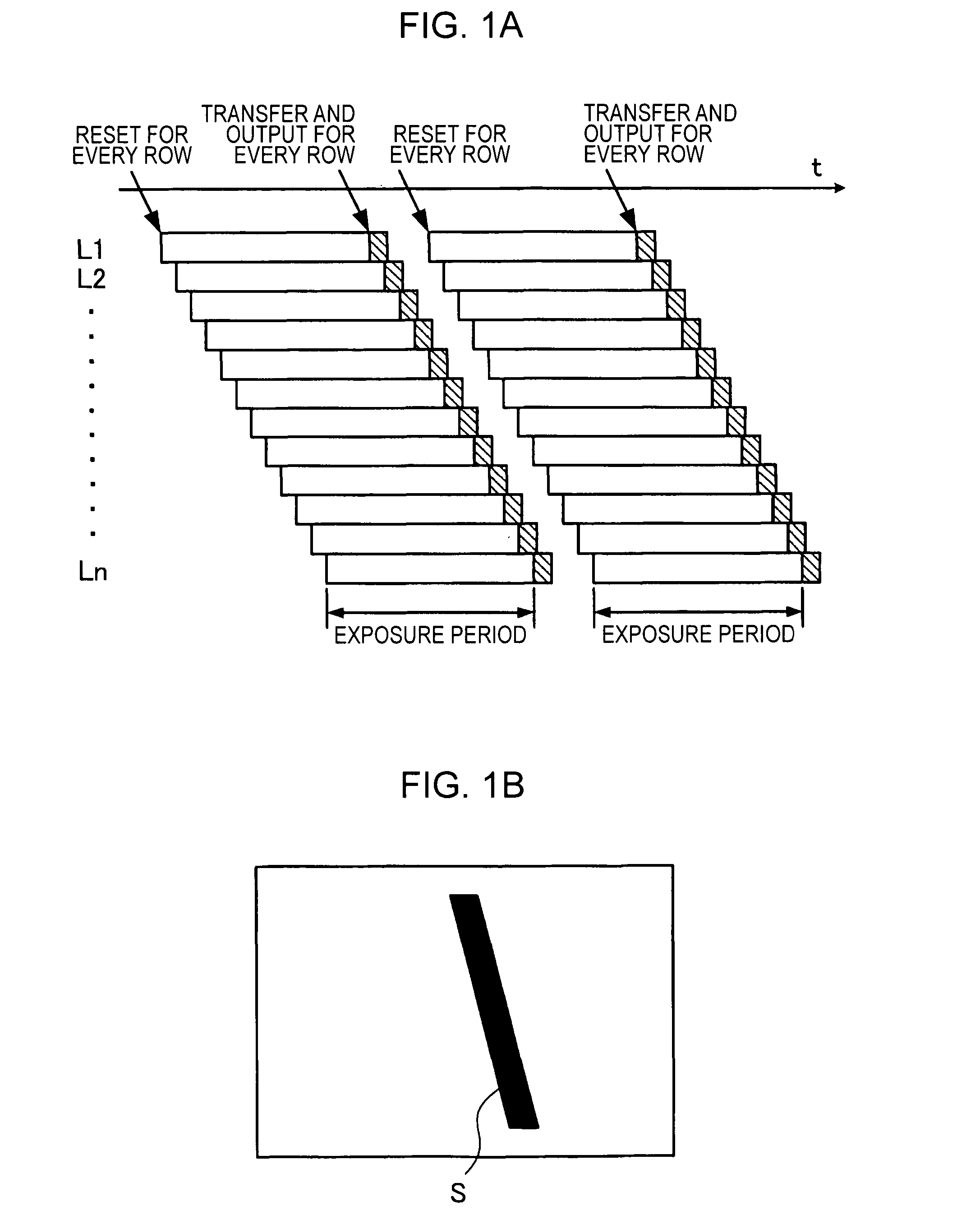
However, the CMOS image sensor capable of simultaneously triggering the shutter for all the rows, described above with reference to FIG. 2, has a problem in that light filters into the FDs 216 after the signal voltage is simultaneously transferred to the FDs 216 for all the rows before the signal voltage is sequentially output for every row to degrade the quality of the capture image because the rows differ in the amount of the filtering light from each other.

Method used


Image

  • Imaging apparatus and imaging method
  • Imaging apparatus and imaging method
  • Imaging apparatus and imaging method

Examples


control example 1

of Shutter Operation

[0090] In the control example 1, the electronic shutter operation in the rolling shutter mode is performed in monitoring of a captured image (in display of a camera through image) and in capture of a motion picture, whereas both the reset operation in the global shutter mode and the exposure-time control operation with the mechanical shutter are used in capture of a still image.

[0091]FIG. 8 is a timing chart showing a shutter operation in the monitoring of a captured image and in the capture of a motion picture.

[0092] It is assumed in FIG. 8 that interlace readout of 30 frames (60 fields) per second is performed. In this case, an image signal corresponding to one field is output from the imaging device 102 in 1 / 60 second. As shown in FIG. 8, after a vertical synchronization signal falls, the FDs 216 and the photodiodes PD11 are sequentially reset for every row in the rolling shutter mode at predetermined timings corresponding to the exposure periods. At the sub...

control example 2

of Shutter Operation

[0104] The control of the shutter operation by the use of both the global shutter and the mechanical shutter, shown in FIG. 9, is not limited to the case where the still image corresponding to one frame is captured. The shutter operation may be controlled by the use of both the global shutter and the mechanical shutter also in continuous capture of still images and in capture of a motion picture.

[0105]FIG. 10 is a timing chart showing a shutter operation in the continuous capture of still images every 1 / 30 second.

[0106] In the control example in FIG. 10, the exposure period is set within one vertical synchronization period (no more than 1 / 60 second) and the pixel signals for all the rows are read out during the subsequent vertical synchronization period to output the image signal corresponding to one frame every 1 / 30 second. In other words, the reset operation for all the rows is simultaneously performed in the global shutter mode at a predetermined timing afte...


PUM


Abstract

An imaging apparatus using a solid-state image sensor that reads out a signal of each pixel by an XY address method to capture an image includes a mechanical shutter configured to block light incident on a light receiving surface of the solid-state image sensor; and control means for simultaneously resetting the pixel signals for all rows in the solid-state image sensor to start exposure to the solid-state image sensor, closing the mechanical shutter after a predetermined exposure period is elapsed, and sequentially reading out the pixel signals for every row of the solid-state image sensor with the mechanical shutter being closed.

Description

CROSS REFERENCES TO RELATED APPLICATIONS [0001] The present invention contains subject matter related to Japanese Patent Application JP 2005-000212 filed in the Japanese Patent Office on Jan. 4, 2005, the entire contents of which are incorporated herein by reference. BACKGROUND OF THE INVENTION [0002] 1. Field of the Invention [0003] The present invention relates to imaging apparatuses and imaging methods using solid-state image sensors to capture images. More particularly, the present invention relates to an imaging apparatus and an imaging method using a solid-state image sensor, such as a complementary metal oxide semiconductor (CMOS) image sensor, which reads out a pixel signal by an XY address method, to capture an image. [0004] 2. Description of the Related Art [0005] Imaging apparatuses, such as digital still cameras and digital video cameras, capable of using solid-state image sensors to capture images and storing the captured images as digital data have been in widespread u...

Claims


Application Information

Patent Timeline
IPC IPC(8): H01L31/062H01L31/113H04N5/225H04N5/335H04N5/353H04N5/357H04N5/374
CPCG03B7/00H04N5/2353H04N5/3532H04N5/359H04N5/3592H04N5/374H04N2101/00H04N23/73H04N25/531H04N25/622H04N25/62H04N25/76H01L27/14612
Inventor HAYASHI, NAOKIASATO, SEISHINTANAKA, KENJI
Owner THOMSON LICENSING SA
Learn More