

Pulse width modulator quantisation circuit
- Summary
- Abstract
- Description
- Claims
- Application Information
AI Technical Summary
Benefits of technology
Problems solved by technology
Method used
Image

Examples
Embodiment Construction
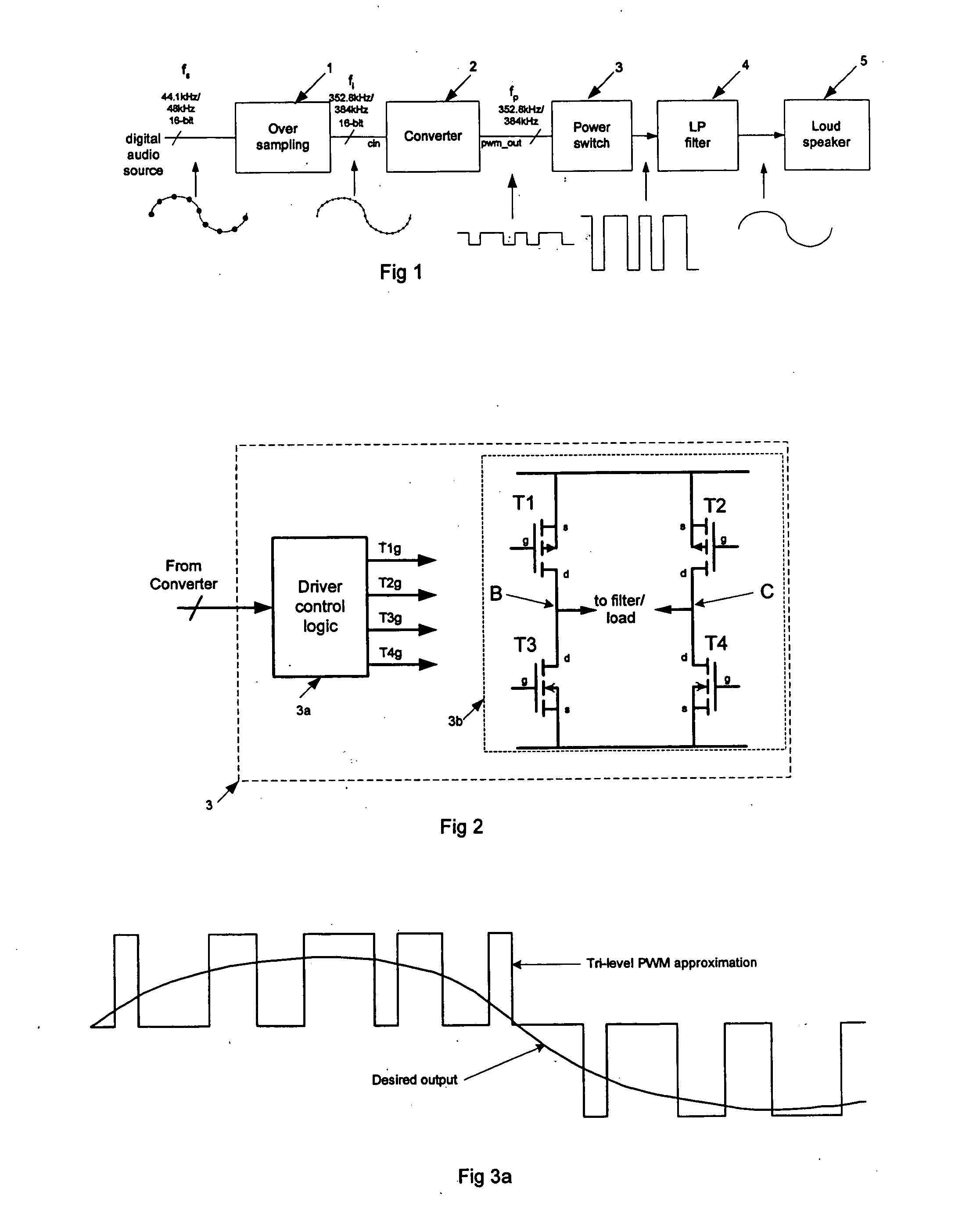
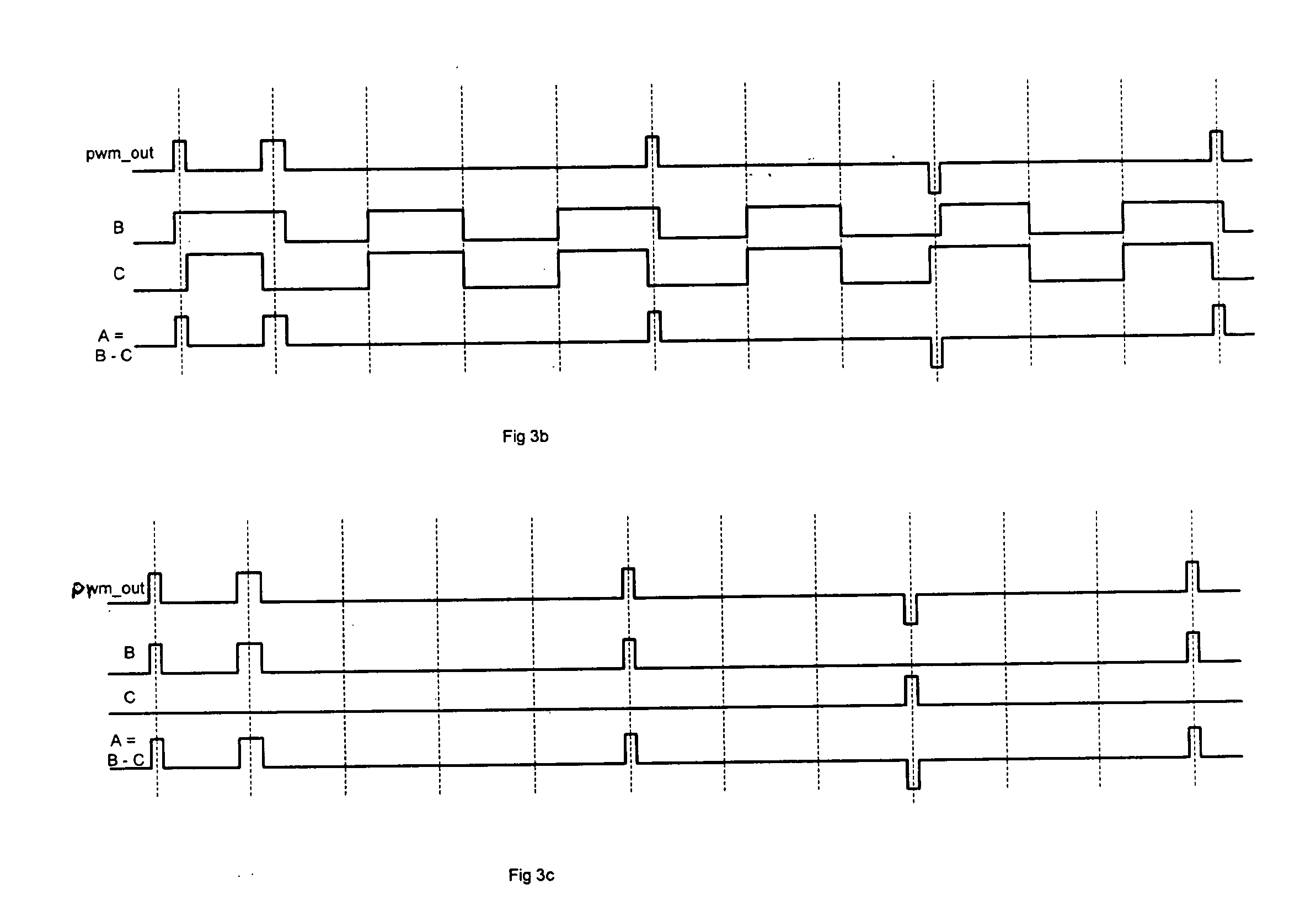
[0055] As discussed previously, the arrangement of FIG. 1 can be used to provide audio output from coded sample values of the original analogue signal. Here pulse width modulation (PWM) techniques are used, in which the sample values are converted into pulses having a width corresponding to the input sample values, and which pulses are used to drive a power switching stage such as illustrated in FIG. 2.
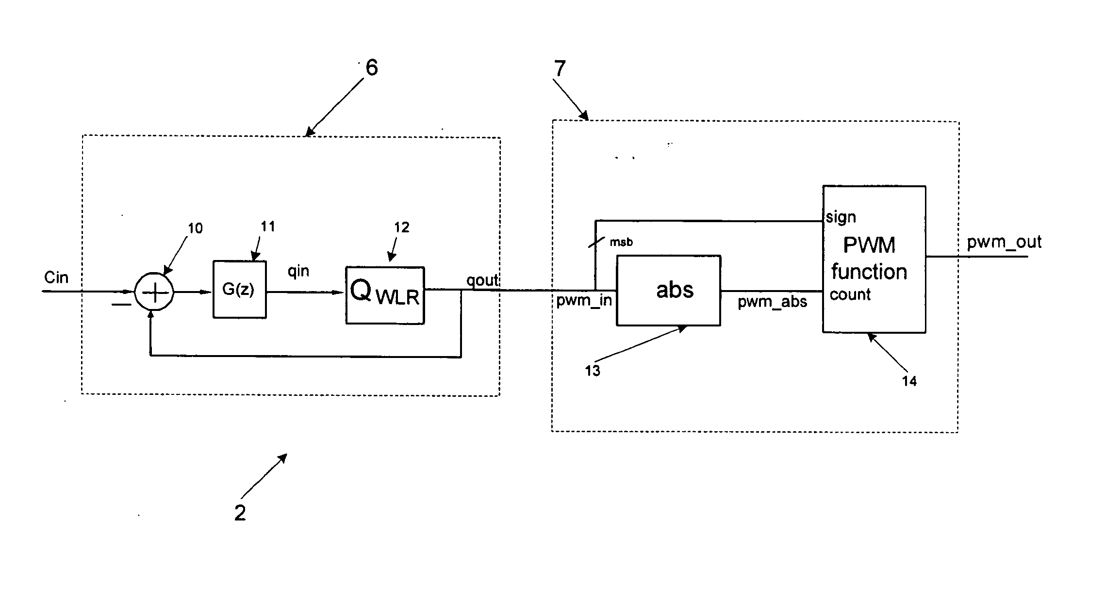
[0056] A PWM converter such as that shown in FIG. 4 is utilised to provide the pulses to drive the switching stage 3. The converter typically utilises a word length reduction circuit 6 coupled to a PWM modulator 7 which provides the actual conversion to pulse width coding.
[0057] In one embodiment a modified word length reduction circuit 16 is provided for use with a tri-level PWM modulator 17 as shown in FIG. 5. Here a guard band quantiser QGB 25 is utilised to modify the output characteristics of the word length reduction circuit 16. The word length reduction circuit 16 also compri...
PUM
 Abstract
Description
Claims
Application Information