Method and system for high-speed precise laser trimming, scan lens system for use therein and electrical device produced thereby

a laser trimming and scanning lens technology, applied in the direction of manufacturing tools, nuclear engineering, therapy, etc., can solve problems such as inability to achiev

Inactive Publication Date: 2006-07-20
ELECTRO SCI IND INC
View PDF22 Cites 40 Cited by
  • Summary
  • Abstract
  • Description
  • Claims
  • Application Information

AI Technical Summary

Benefits of technology

[0015] An object of the present invention is to provide an improved method and system for high-s...

Problems solved by technology

However, considering increased lens aberrations a...

Method used


Image

  • Method and system for high-speed precise laser trimming, scan lens system for use therein and electrical device produced thereby
  • Method and system for high-speed precise laser trimming, scan lens system for use therein and electrical device produced thereby
  • Method and system for high-speed precise laser trimming, scan lens system for use therein and electrical device produced thereby

Examples


Embodiment Construction

)

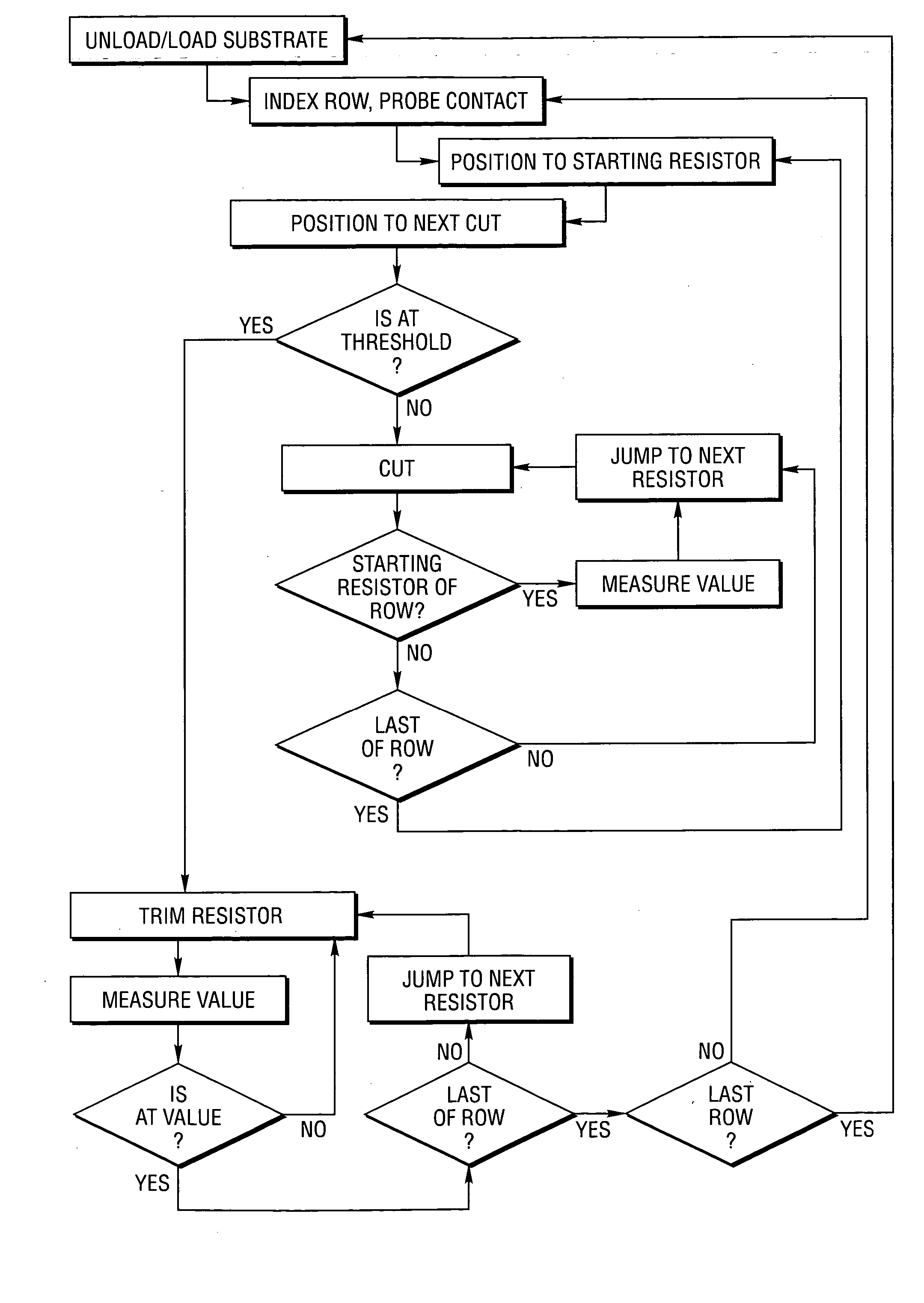
High-Speed Serpentine Trimming Process

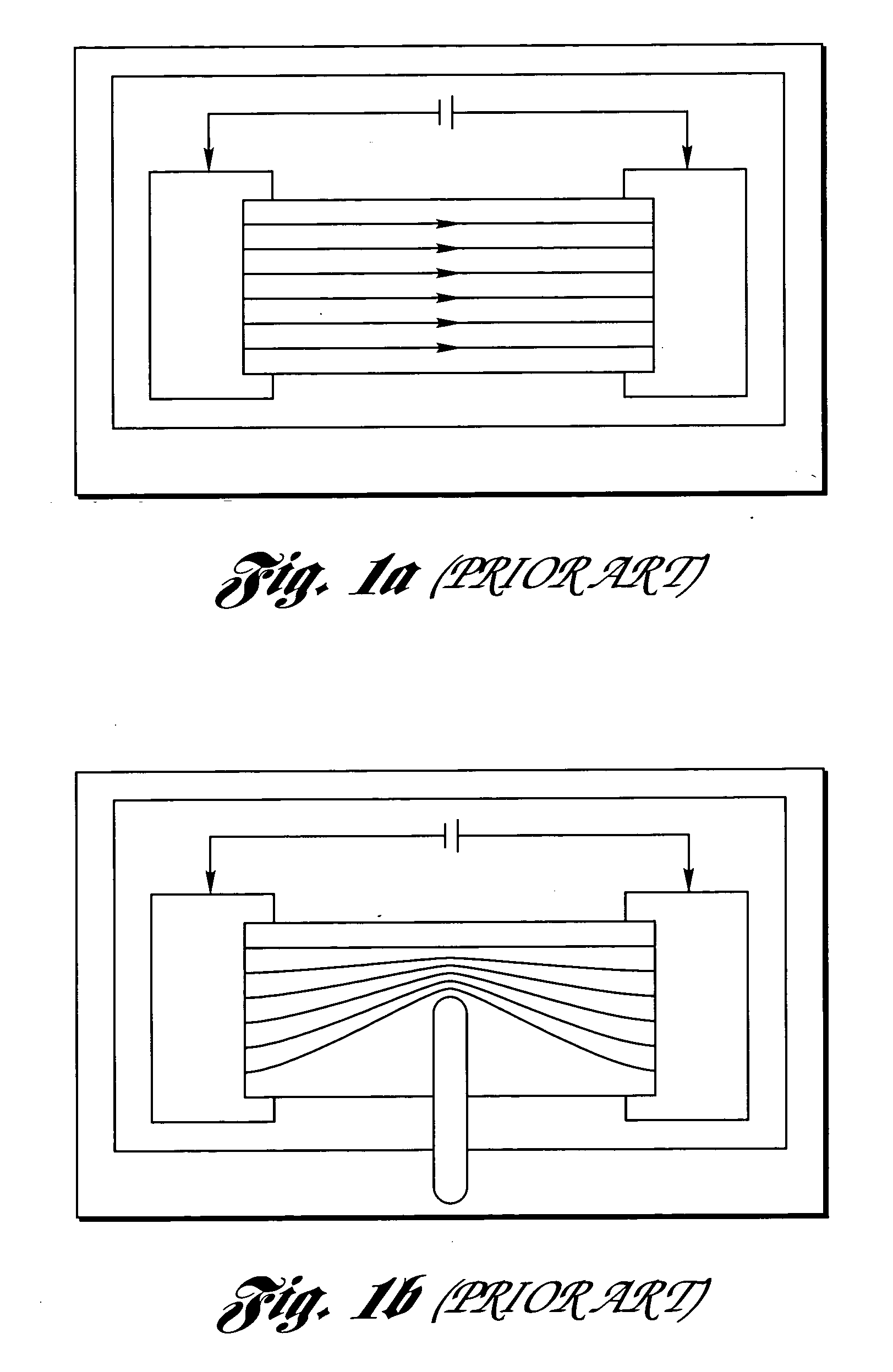
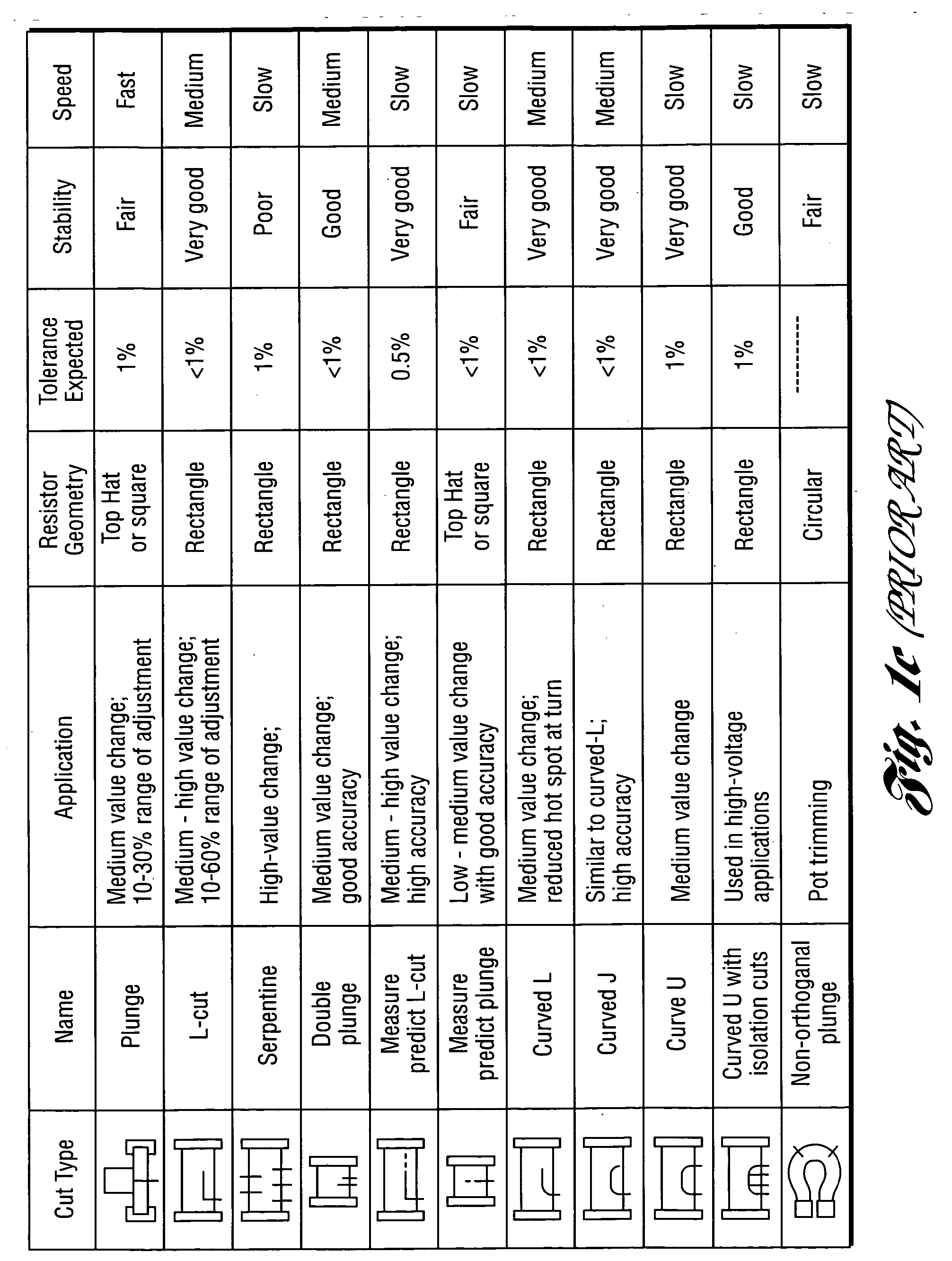
[0085] In resistor trimming, the cuts direct the current flowing through the resistive material along a resistance path. Fine control and adjustment of the cut size and shape change the resistance to a desired value, as illustrated in FIGS. 1a-1c. Typically, chip resistors are arranged in rows and columns on a substrate. FIG. 2a shows an arrangement wherein a row of resistors R1, R2, . . . RN is to be processed. A probe array, having a probe 200 and depicted by arrows in FIG. 2a, is brought into contact 202 with the conductors of a row of resistors. A matrix switch addresses the contacts for a first pair of conductors (e.g.: contacts across R1) and a series of cuts and measurements is performed to change the resistance between the conductor pair to a desired value. When the trimming of a resistor is complete. the matrix switches to a second set of contacts at the next row element (e.g.: R2) and the trimming process is repeated. When a complet...


PUM

PropertyMeasurementUnit
Lengthaaaaaaaaaa
Lengthaaaaaaaaaa
Lengthaaaaaaaaaa

Abstract

A method, system and scan lens system are provided for high-speed, laser-based, precise laser trimming at least one electrical element. The method includes generating a pulsed laser output having one or more laser pulses at a repetition rate. Each laser pulse has a pulse energy, a laser wavelength within a range of laser wavelengths, and a pulse duration. The method further includes selectively irradiating the at least one electrical element with the one or more laser pulses focused into at least one spot having a non-uniform intensity profile along a direction and a spot diameter as small as about 6 microns to about 15 microns so as to cause the one or more laser pulses to selectively remove material from the at least one element and laser trim the at least one element while avoiding substantial microcracking within the at least one element. The wavelength is short enough to produce desired short-wavelength benefits of small spot size, tight tolerance and high absorption, but not so short so as to cause microcracking.

Description

CROSS-REFERENCE TO RELATED APPLICATIONS [0001] This application claims the benefit of U.S. provisional application Ser. No. 60 / 617,130, filed Oct. 8, 2004, entitled “Laser System And Method For Laser Trimming.” This application also claims priority to and is a continuation-in-part application of U.S. patent application Ser. No. 11 / 131,668, entitled “Method And System For High-Speed Precise Micromachining An Array Of Devices,” filed May 18, 2005, which is a divisional of Ser. No. 10 / 397,541, entitled “Method And System For High-Speed Precise Micromachining An Array Of Devices,” filed Mar. 26, 2003, which is a continuation-in-part application of U.S. patent application Ser. No. 10 / 108,101, entitled “Methods And Systems For Processing A Device, Methods And Systems For Modeling Same And The Device,” filed Mar. 27, 2002, now published U.S. patent application No. 2002 / 0162973. U.S. Pat. No. 6,341,029, entitled “Method and Apparatus for Shaping a Laser-Beam Intensity Profile by Dithering,”...

Claims


Application Information

Patent Timeline
IPC IPC(8): H01L21/78A61N5/00H01L21/301
CPCB23K26/063B23K26/0807H01C17/242B23K26/082B23K26/0622
Inventor GU, BOLENTO, JOSEPH V.EHRMANN, JONATHAN S.COUCH, BRUCE L.CHU, YUN FEEJOHNSON, SHEPARD D.
Owner ELECTRO SCI IND INC
Why Eureka
Try Eureka