Difference correcting method for posture determining instrument and motion measuring instrument

a technology of motion measurement and difference correction, which is applied in the direction of instruments, turn-sensitive devices, person identification, etc., can solve the problems of zero point voltage fluctuation and accumulation of errors, and achieve the effect of convenient attachment of the motion determining instrument and more accurate motion measuremen

Inactive Publication Date: 2006-07-20
AKEBONO BRAKE IND CO LTD +1
View PDF0 Cites 53 Cited by
  • Summary
  • Abstract
  • Description
  • Claims
  • Application Information

AI Technical Summary

Benefits of technology

[0034] A state of caring / rehabilitation / work (posture) is measured and represented by a numerical value. This is a system for measuring a motion of a patient to check a treatment effect or quantitatively understand a progressing situation, thereby supporting technique improvement or the like. This is also a system for analyzing a three-dimensional motion of an athlete or a dancer, thereby supporting improvement of techniques etc.
[0035] When the motion determining instrument equipped with the acceleration sensor and the angular velocity sensor is attached to the human body, acquisition of the sensor attaching angle to the limb of the human body and the relative positional relation between the external coordinate system which becomes a reference for human body motion measurement and the sensor based on a relative relation between the direction of gravity obtained from the acceleration sensor and a specific human body posture which becomes a reference facilitates the attaching of the motion determining instrument to the human body.
[0036] According to the present invention, with the foregoing configuration, it is possible to properly correct the error caused by the drift phenomenon. As a result, more accurate motion measurement can be carried out.

Problems solved by technology

As described above, however, this zero point voltage fluctuates because of an influence of external disturbances such as an environmental temperature of the sensor.
Thus, errors accumulate, resulting in data of a value indicating a state completely different from original real data after a passage of predetermined time.

Method used


Image

  • Difference correcting method for posture determining instrument and motion measuring instrument
  • Difference correcting method for posture determining instrument and motion measuring instrument
  • Difference correcting method for posture determining instrument and motion measuring instrument

Examples


example

[0088] Next, a specific example of measuring a motion of a lower body and reproducing a sitting motion of a human on a chair in a computer will be described.

1.) Experiment Instrument

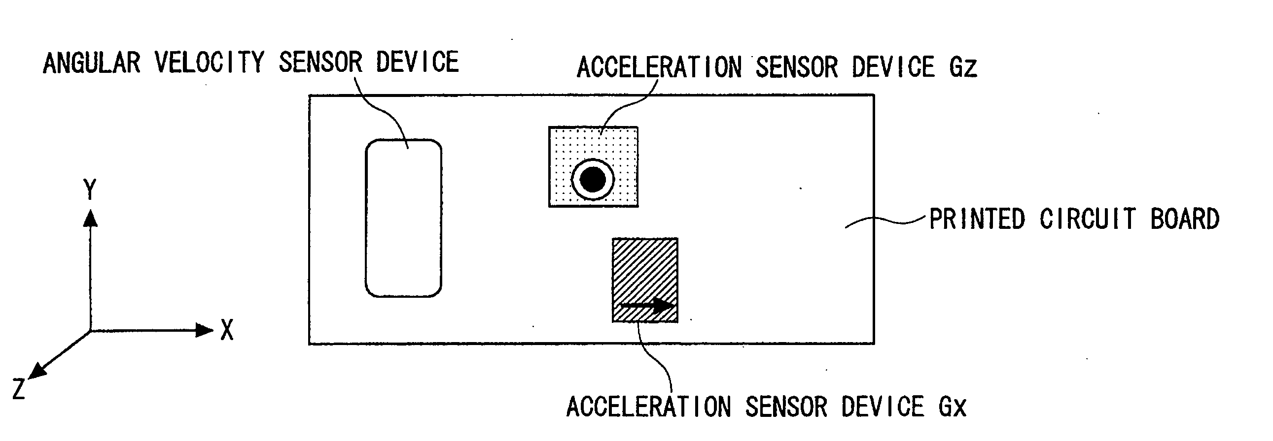
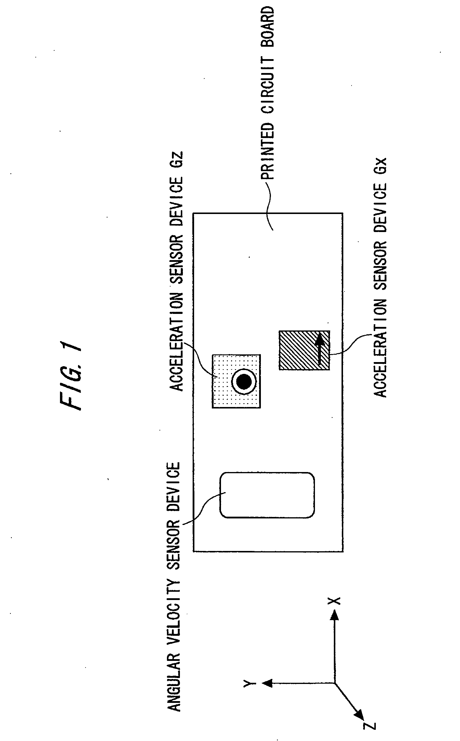
[0089] As described above, such a sensor box was manufactured and used that three combine sensor substrates including two acceleration axes and one yaw rate axis were used, and an acceleration sensor and yaw rate sensor were arranged to be three-dimensionally orthogonal to each other, thereby enabling acquisition of outputs of three acceleration axes and three yaw rate axes. An output from each sensor was fetched in a notebook PC by an AD conversion card, DAQCard-6024E, manufactured by National Instrument Inc.

2) Attachment of Sensor Box

[0090] Five compact sensor boxes were attached to respective portions (waist, left and right thighs, and left and right lower thighs) shown in FIG. 10 by using supporters or magic tapes (registered trademark).

[0091] In FIG. 10, ∘ indicates a joint (joint portion), a...


PUM


Abstract

The error of a sensor in motion capture system is corrected. An acceleration sensor determines the direction of gravity (G1) in a still initial state. The direction G1 will never change always if a drift dose not occur. However, actually if an object to which an acceleration sensor is attached moves along a coordinate axis, the direction gradually changes due to a drift with time. According to the invention, after a given time has passed, the acceleration sensor is stopped to determine the direction of gravity. Referring to the data on this determination, the true direction of gravity to be judged is compared with the direction of gravity G1 influenced by the drift. The difference between them is assumed to be an error due to a drift, and the error is subtracted from the determined value to correct the error of the measurement value. Similarly to the direction of gravity, assuming that there is an error in any direction in the coordinate system, the errors are corrected, and more accurate motion determination is possible.

Description

TECHNICAL FIELD [0001] The present invention relates to a so-called motion capture system which measures an operation of a target based on data from a sensor attached to a human or another moving object, and further to an operation determining instrument used for the system, in particular, an instrument having a feature in a correcting method of its determination data. BACKGROUND ART [0002] Conventional technologies for measuring motions of human bodies or the like are classified into a method of installing a sensor in a place away from a measuring target to measure it (method by remote measurement), and a method of attaching a sensor to a measuring target itself to measure its motion without relying on a signal or the like from the outside (method by autonomous measurement). [0003] As the method by the remote measurement, there are a method of using an optical image sensor (e.g., JP2000-182058A, JP2002-8043 A, or JP 10-74249 A), a method of using a magnetic sensor, and the like. [0...

Claims


Application Information

Patent Timeline
Patent Type & Authority Applications(United States)
IPC IPC(8): G01P21/00G01C17/38G06F19/00A61B5/11G01B21/00G01C19/56G01C19/5607G01P15/18
CPCA61B5/11A61B5/1116A61B2562/0219G01C19/5607A61B5/6828A61B5/6814A61B5/6824A61B2560/0223
Inventor SHIBASAKI, RYOSUKEKONISHI, YUSUKEKANASUGI, HIROSHIYOSHIDA, NOBUYUKI
Owner AKEBONO BRAKE IND CO LTD
Why Eureka
Try Eureka