Method for the activation of a tank venting valve of a motor vehicle during a leak test

a technology for venting valves and motor vehicles, which is applied in the direction of fluid tightness measurement, combustion air/fuel air treatment, instruments, etc., to achieve the effect of uniform vacuum build-up time, minimizing deviation, and improving the accuracy of tank filling levels determined

Active Publication Date: 2006-07-27
VITESCO TECH GERMANY GMBH
View PDF7 Cites 11 Cited by
  • Summary
  • Abstract
  • Description
  • Claims
  • Application Information

AI Technical Summary

Benefits of technology

[0008] This ensures that for the same tank filling level and a leak-tight tank venting system a uniform vacuum build-up time can be adhered to. Should differences in the time taken to reach the vacuum threshold be measured during the vacuum build-up for the same tank filling level, these are definitely attributable to a leak. The method for leak testing of the tank venting system therefore functions more reliably.
[0009] The method according to the invention affords a further advantage when the quantity of fuel present in the tank, that is the tank filling level, is to be determined from the time it takes to reach a set vacuum threshold. Determination of the tank filling level is based on the consideration that with a lower filling level the volume of fu

Problems solved by technology

Should differences in the time taken to reach the vacuum threshold be measured during the v

Method used


Image

  • Method for the activation of a tank venting valve of a motor vehicle during a leak test
  • Method for the activation of a tank venting valve of a motor vehicle during a leak test
  • Method for the activation of a tank venting valve of a motor vehicle during a leak test

Examples


Embodiment Construction

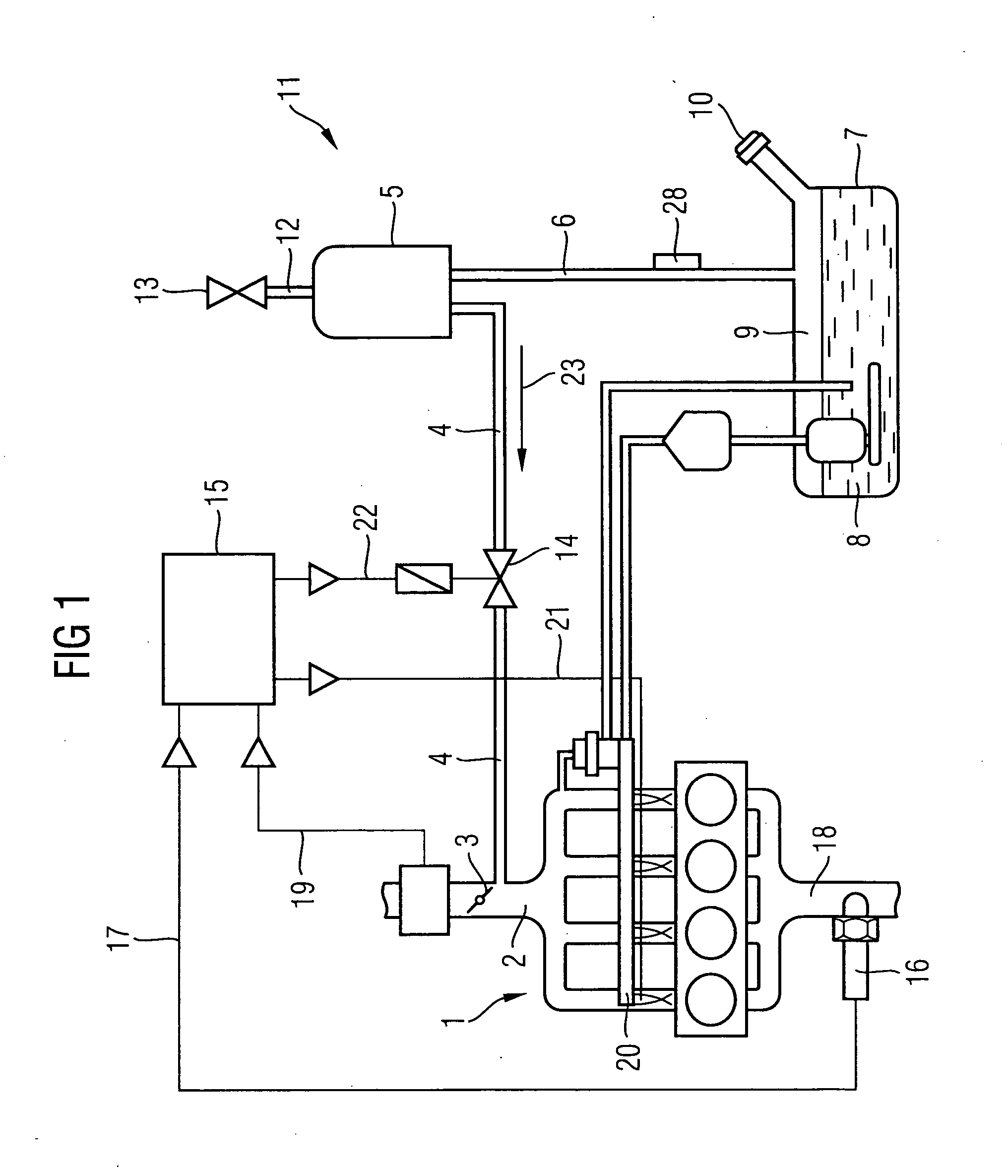
[0034] The motor vehicle internal combustion engine 1 represented in FIG. 1 has an intake manifold 2 in which a throttle valve 3 is situated. The intake manifold 2 is connected by way of a recovery line 4 to a retention vessel 5 of a tank venting system, and the retention vessel 5 is in turn connected by way of a venting pipe 6 to a fuel tank 7. The fuel gas 9 which has accumulated above the liquid fuel 8 situated in the fuel tank 7 passes via the venting pipe 6 into the retention vessel 5, where it is caught in an activated charcoal filter. The fuel tank 7 is closed by a fuel filler cap 10. The retention vessel 5 is connected to the external atmosphere 11 by a ventilation pipe 12. This connection may be interrupted by a shut-off valve 13. A tank venting valve 14 is arranged in the recovery line 4. Multiple sensor variables of the internal combustion engine, such as the air-fuel ratio 17 of the exhaust gas leaving the internal combustion engine via an exhaust system 18, which is mea...


PUM


Abstract

The invention relates to a method for regulating a fuel tank venting valve of a motor vehicle during leak testing of a fuel tank venting system where the fuel tank venting valve is arranged in a recovery line that connects a retention vessel to catch fuel vapors from a fuel tank to an inlet manifold of an operating internal combustion engine, comprising sealing the tank venting system from the atmosphere outside the motor vehicle, opening the fuel tank venting valve to expose the fuel tank and the tank venting system to a relative negative pressure present in the inlet manifold of the operating internal combustion engine and regulating the degree of opening of the tank venting valve based upon the external pressure, pA.

Description

CROSS REFERENCE TO RELATED APPLICATIONS [0001] This application claims the benefits of German Patent application No. 10 2005 003 924.3 filed Jan. 27, 2005, all of the applications are incorporated by reference herein in their entirety FIELD OF THE INVENTION [0002] The invention relates to a method for the activation of a tank venting valve of a motor vehicle during leak testing of a tank venting system, the tank venting valve being arranged in a recovery line, which connects a retention vessel catching fuel vapors from a fuel tank to an inlet manifold of an internal combustion engine, and the tank venting system being sealed off airtightly from the atmosphere prevailing outside the motor vehicle and the tank venting valve being opened in order to build up a vacuum in the tank venting system and in the fuel tank connected to the retention vessel by way of a venting pipe, and closed again once a vacuum threshold has been reached. BACKGROUND OF THE INVENTION [0003] Such a method is dis...

Claims


Application Information

Patent Timeline
IPC IPC(8): G01M19/00F02M33/02G01M99/00
CPCF02M25/0809F02M25/0836F02M25/089
Inventor GRUNWALD, OLIVERLUDWIG, WOLFGANGWIESE, MATTHIAS
Owner VITESCO TECH GERMANY GMBH
Why Eureka
Try Eureka