Motor actuator

Inactive Publication Date: 2006-07-27
ASMO CO LTD +1
View PDF4 Cites 13 Cited by
  • Summary
  • Abstract
  • Description
  • Claims
  • Application Information

AI Technical Summary

Benefits of technology

[0009] The present invention addresses the above disadvantages. Thus, it is an objective of the present invention to provide a motor actuator that has a

Problems solved by technology

However, in Japanese Unexamined Patent Publication H5-252692, a space is required to allocate the position detection sensor.
Thereby, this is disadvantage for reducing a size of the motor actuator.
Also, a number of constituent members for the position detection sensor is increased, and as a result, an assembling process becomes complex.
However, a degree of accuracy for

Method used


Image

  • Motor actuator
  • Motor actuator
  • Motor actuator

Examples


first embodiment

[0029] The first embodiment of the present invention will be described with reference to the accompanying drawings.

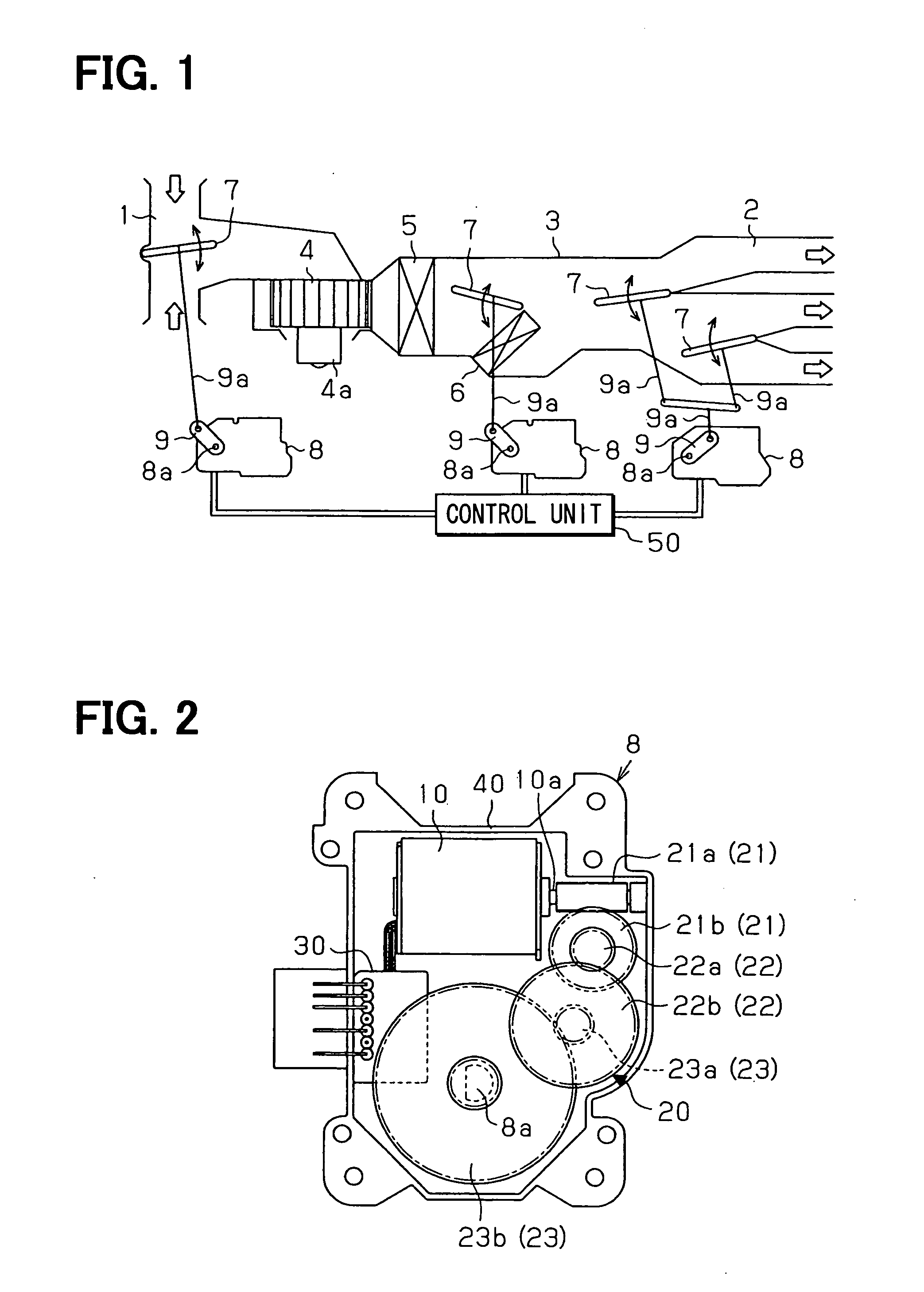
[0030] A vehicle air conditioner has an air-conditioning duct 3, which includes inlet ports 1 for drawing air and outlet ports 2 for blowing out air into a vehicle compartment. The air conditioner also has a blower fan 4, an evaporator 5, a heater core 6 and dampers 7 in the air-conditioning duct 3. Outside air (i.e., air outside the vehicle compartment) or inside air (i.e., air inside the vehicle compartment) is supplied to the air-conditioning duct 3 through the inlet ports 1 by the blower fan 4, which is driven by a blower motor 4a. The air supplied to the air-conditioning duct 3 is dehumidified and cooled through the evaporator 5. Opening degrees of the dampers 7 are changed to selectively open and close the inlet ports 1 and the outlet ports 2 so that an airflow passage in the air-conditioning duct 3 is changed. The outside air or / and inside air can be drawn throu...

second embodiment

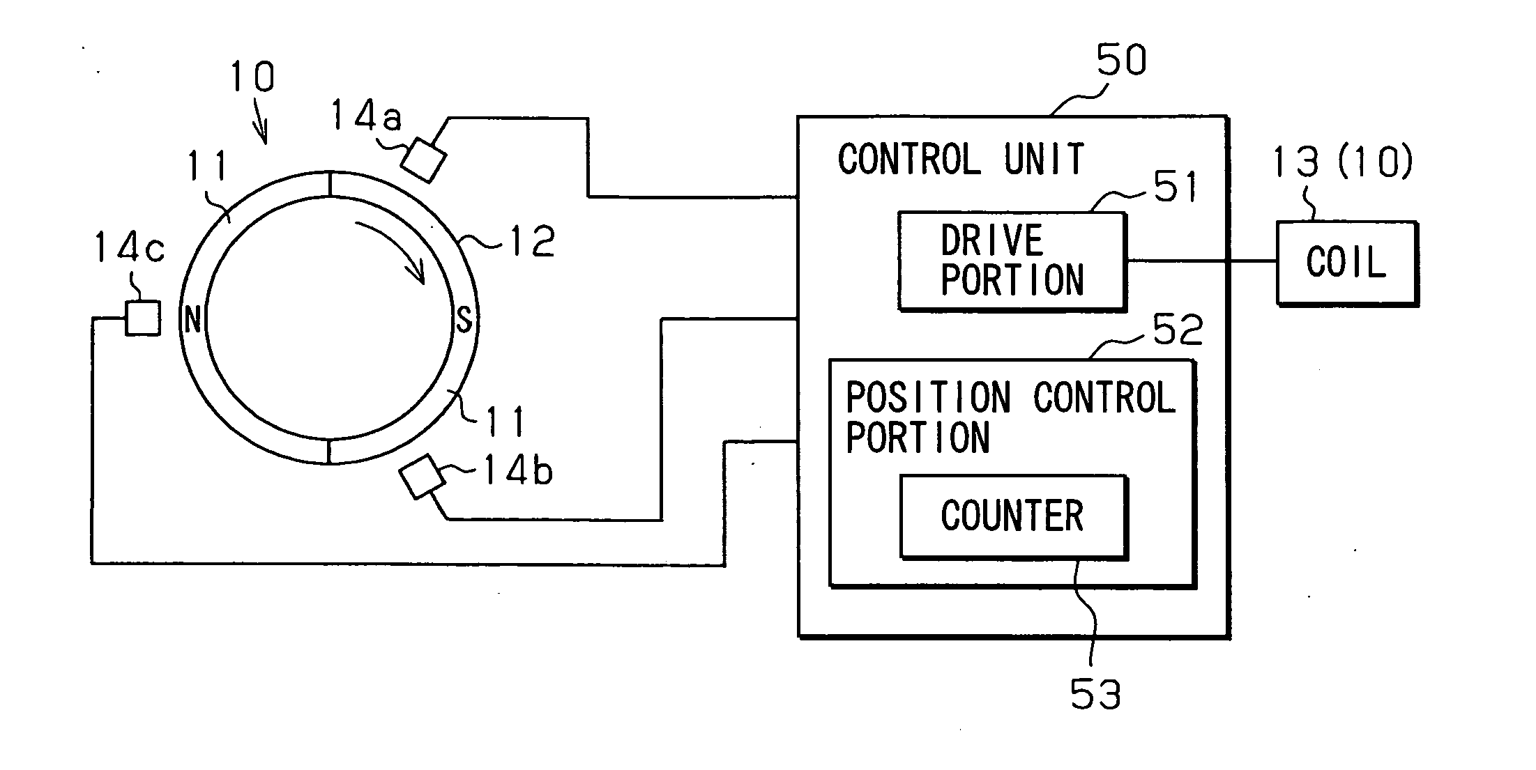
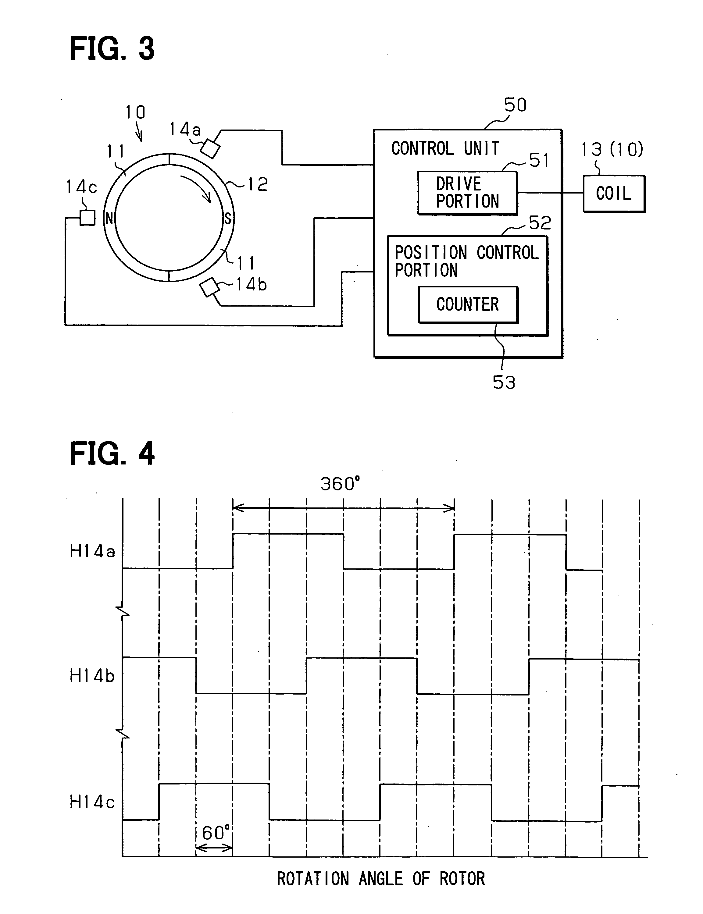
[0063] The second embodiment of the present invention will be described with reference to FIGS. 6 to 8. Components of a motor actuator 60 of the second embodiment, which are similar to the components of the motor actuator 8 of the first embodiment, will be indicated by the same numerals. Different features from the first embodiment will be mainly described. In FIG. 7, the brushless motor 10, the magnet 11, the rotor 12 and the coil 13 are omitted for simply indicating the drawing.

[0064] As shown in FIG. 6, the motor actuator 60 according to the second embodiment includes the brushless motor 10, the speed reducing portion 20, a circuit board 62 structuring a control unit 61. The motor actuator 60 autonomously controls the damper 7 (see FIG. 1) serving as a driven member, based on control signals outputted from an air-conditioning electronic control unit (ECU) 70. The circuit board 62 is fixed to a case 63 in such a manner that a part of the circuit board 62 faces an end face of the ...


PUM


Abstract

A motor actuator for actuating a driven member includes a control unit and a brushless motor, which includes a coil, a magnet and a hall element. The coil generates a magnetic field when being energized. The magnet rotor is rotatable in the magnetic field generated by the coil. The hall element detects a variation in the magnetic field due to rotation of the magnet rotor. Then, the hall element outputs an output signal according to the variation in the magnetic field. The control unit detects a relative position between the magnet rotor and the coil based on the output signal outputted from the hall element, and controls energization of the coil based on the relative position. Furthermore, the control unit detects a location of the driven member, and controls the brushless motor to drive the driven member based on a rotation amount of the magnet rotor.

Description

CROSS REFERENCE TO RELATED APPLICATION [0001] This application is based on and incorporates herein by reference Japanese Patent Applications No. 2005-16045 filed on Jan. 24, 2005 and No. 2005-310099 filed on Oct. 25, 2005. BACKGROUND OF THE INVENTION [0002] 1. Field of the Invention: [0003] The present invention relates to a motor actuator for actuating a driven member (e.g., a damper used for a vehicle interior air conditioning), which is positioned based on a rotation amount of a driving member (e.g., brushless motor). [0004] 2. Description of Related Art: [0005] Conventionally, an air-amount adjusting damper for a vehicle air conditioner is actuated by a motor actuator having a control mechanism, which controls an opening degree of the damper based on a rotation amount of a motor serving as a driving member of the motor actuator. The motor actuator includes a position detection sensor, such as a potentiometer, a cam switch and an encoder, which detects the rotation amount of the ...

Claims


Application Information

Patent Timeline
IPC IPC(8): H02P25/12H02K7/116B60H1/00H02P6/06H02P6/08H02P6/16H02P6/17
CPCH02P25/12
Inventor KUJIRA, YUKINOBUINAYOSHI, TAKAHIROTAKEUCHI, TOKUHISA
Owner ASMO CO LTD
Why Eureka
Try Eureka