Production of synthesis gas

a technology of synthesis gas and gasification process, which is applied in the direction of gasification process details, combustible gas purification/modification, combustible gas production, etc., can solve the problems of not achieving optimal slag/unconverted carbon separation, significant economic loss in feedstock cost, etc., to reduce feedstock consumption, eliminate use, and increase the effect of gasification process efficiency

Inactive Publication Date: 2006-07-27
EASTMAN CHEM CO
View PDF22 Cites 34 Cited by
  • Summary
  • Abstract
  • Description
  • Claims
  • Application Information

AI Technical Summary

Benefits of technology

[0011] (3) feeding water slurry stream (2) produced in step (2) to the gasification zone. Our novel process increases the efficiency of the gasification process, decreases feedstock consumption by up to 10%, and eliminates the use of expensive solid handling equipment such as front end loaders or slag drag conveyors, without causing operation swings that are detrimental to syngas production.

Problems solved by technology

Furthermore, the loss of unconverted or incompletely converted carbonaceous or hydrocarbon feedstock in the slag effluent represents a significant economic loss in the cost of feedstock.
While some separation of the ash and unconverted carbon is being conducted by this process, the process is conducted under pressure, requires cooling of the water, and may not achieve optimal slag / unconverted carbon separation.

Method used


Image

  • Production of synthesis gas

Examples


example

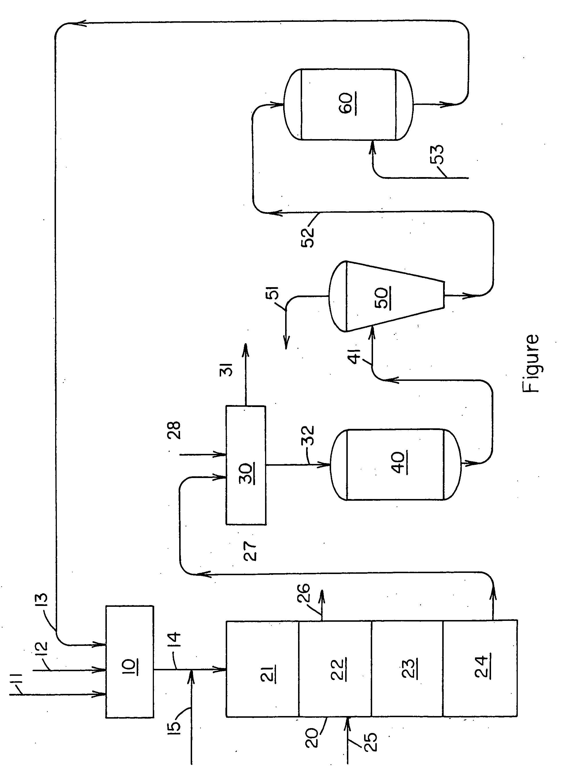
[0035] The operation of the process provided by the present invention is further illustrated by the following example utilizing the process flow diagram of the accompanying FIGURE. Central Appalachian Coal is the feedstock used in the example. All percentages given in the example are by weight unless otherwise specified.

[0036] Feedstock coal and water are fed to grinding mill 10 via conduits 11 and 12, respectively. A slurry of recovered carbon values also is fed to grinding mill 10 via conduit 13. The particle size of the feedstock coal is reduced to less than about 3 mm in the grinding mill. The slurry of coal and recycled carbon values is fed via conduit 14, along with substantially pure oxygen provide by conduit 15, to gasification zone 20 consisting of partial oxidation reactor zone 21, quench zone 22, lockhopper zone 23 and gasification slag effluent sump 24. Water is fed via conduit 25 to quench zone 22 to cool the slag effluent and product syngas which is removed from gasif...


PUM

PropertyMeasurementUnit
particle sizeaaaaaaaaaa

Abstract

Disclosed are gasification processes for the production of mixtures of carbon monoxide and hydrogen, by the partial oxidation of a carbonaceous feedstock material wherein carbon values contained in a solid slag effluent from the partial oxidation reactor are recovered and recycled to the gasification reactor.

Description

FIELD OF THE INVENTION [0001] This invention pertains to gasification processes for the production of mixtures of carbon monoxide and hydrogen, by the partial oxidation of a carbonaceous feedstock material. More specifically, the present invention pertains to a process for the production of carbon monoxide and hydrogen wherein carbon values contained in a solid slag effluent from the partial oxidation reactor are recovered and recycled to the gasification reactor. BACKGROUND OF THE INVENTION [0002] Gasification is among the cleanest and most efficient technologies for the production of power, chemicals and industrial gases from carbonaceous or hydrocarbon feedstocks, such as coal, heavy oil, and petroleum coke. Gasification converts hydrocarbon feedstocks into clean synthesis gas, or syngas, composed primarily of hydrogen (H2) and carbon monoxide (CO). Syngas is a feedstock for making a host of useful organic compounds or can be used as a clean fuel to produce power by an environmen...

Claims


Application Information

Patent Timeline
Patent Type & Authority Applications(United States)
IPC IPC(8): C01B31/00
CPCC10J3/466C10J3/84C10J2300/0906C10J2300/093C10J2300/0946C10J2300/0973C10J2300/0983C10J2300/1631C10J2300/1807C10J2300/1846C10K1/10C10K1/101
Inventor BROOKER, DONALD DUANEBAYS, JOSEPH NATHANIEL
Owner EASTMAN CHEM CO
Why Eureka
Try Eureka